D-2.2 Install Valves
Now that you understand the types and purpose of valves, the next step is learning how to install them correctly. Proper valve installation is important for safe operation. The location and position of a valve in a piping system can affect how it works.
 ALWAYS follow the manufacturer’s installation instructions when installing a valve.
General Valve Installation Guidelines
Accessibility
Valves need to be easily accessible for regular maintenance, replacement, or inspection. Some valves have gauges or indicators that must be visible and accessible, as they are used to adjust valve operation. There should always be enough headroom to dismantle the valve stem or spindle and to repack or replace the packing in the stuffing box. Easy access is important to enable consistent lubrication of moving parts and, in some valves, the replacement of seats, seals, bonnets, or disks.
Installation
Valves may be joined to piping by screwed, welded, sweated, or flanged joints. Always follow these precautions during installation:
- Screw-joint valves: Place your wrench on the valve end into which a pipe is inserted. This prevents excessive strain and potential damage on the valve body.
- Globe-type valves with sweated or welded joints: Make sure the valve stem is backed off or removed so that the disk will not be damaged.
- Unions or flanges are often installed between valves and equipment to make repairs easier. Make sure that valves are aligned correctly with the flanges or unions. Misalignment can place undue strain on the valve.
Code Requirements for Valve Installation
Be sure to check codes and municipal bylaws for regulations that are pertinent to your location and application.
Globe Valve Installation
In piping systems that must be drained in freezing weather, globe valves should be positioned with the stem or spindle vertically up or horizontal to ensure that water does not remain inside the valve. Avoid installing a valve with the valve stem facing down, especially if it will be exposed to freezing conditions.
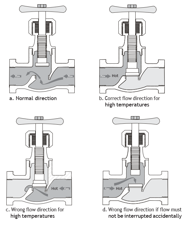
The position of globe and angle valves depends on operating conditions. Flow should be from underneath the disk when continuous flow is critical to safe operation (Figure 1a). If water flow is directed onto the top of the disk and the disk becomes separated from the stem, flow may stop completely (Figure 1d). When handling high-temperature fluids, cooling of the valve stem can cause contraction away from the valve seat when it cools down (Figure 1c). Fluid will find its way past the seat and continue to leak even if the valve was closed tight when the valve was hot. Figure 1b shows the valve correctly installed to keep the valve stem warm and closed.
Stop and Waste Valve Installation
Stop and waste valves allow water on the downstream side of the valve seat to drain when the valve is shut. These valves are sometimes referred to as stop and drain valves.
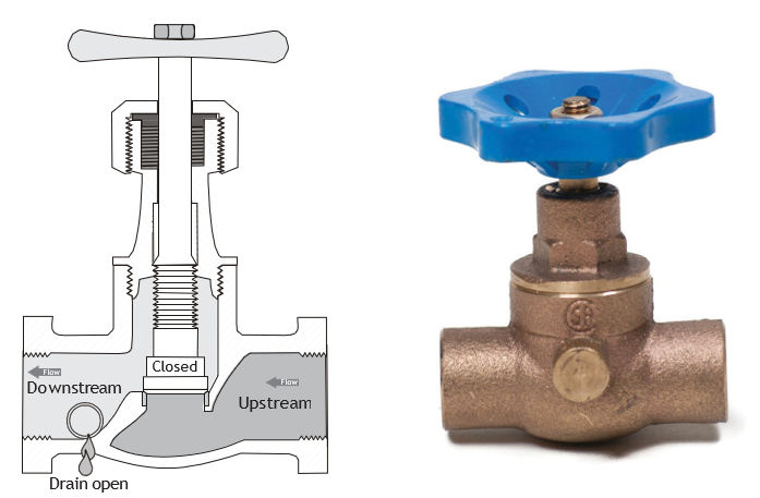
Stop and waste valves must be installed so that the drain is on the downstream side of the valve seat. They are typically installed directly inside the building on the water service connection to the rest of the building. They are often used when a water pipe supplies an outside hose valve. The stop and drain is installed in other locations where freezing conditions require the system to be shut down and drained for winterization.
Gate Valve Installation
Gate valves must be installed with the stem vertical or at an angle (Figure 3), but not less than horizontal, as debris can collect in the bonnet (Figure 4). The exception is solid wedge gate valves, which can be installed in any position if there is no alternative.
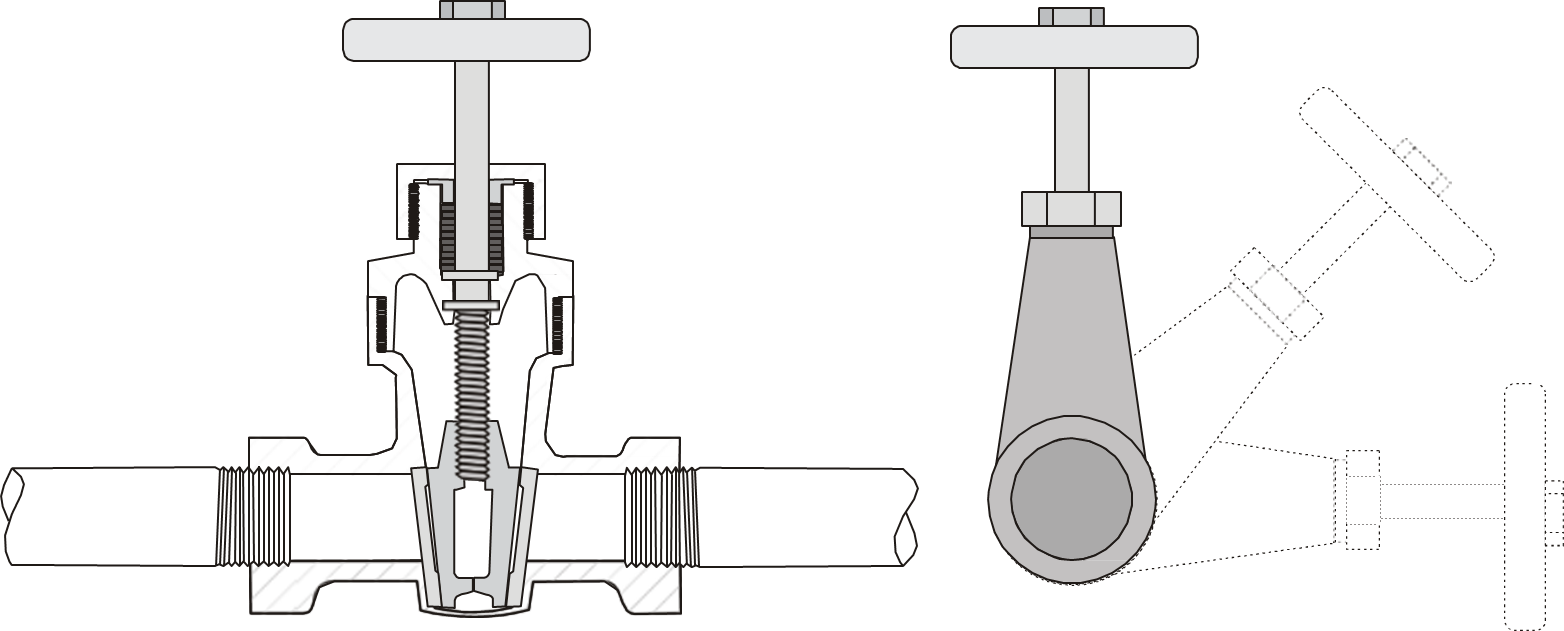
Solid wedge gates can be installed in any position. (BC Industry Training Authority, 2019). CC BY-NC-SA 4.0
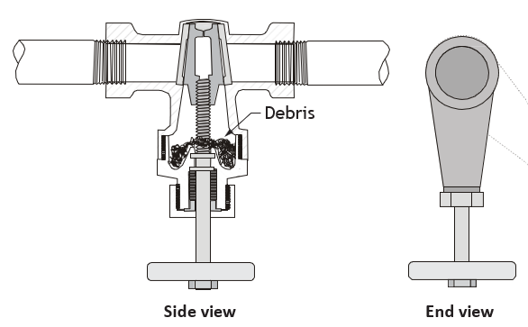
Do not install parallel disk gate valves with the stem facing down.
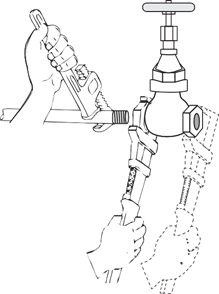
When installing threaded valves, place your wrench on the end of the valve that you are screwing onto the pipe (Figure 5). Never tighten with the wrench on the opposite end of the valve. Tightening this way would subject the valve body to force that could deform it and prevent the valve from operating correctly.
Use a flat-jawed wrench to tighten the valve when the ends are shaped for flat-jawed wrenches.
Check Valve Installation
Check valves should be installed away from other valves and fittings to avoid excessive turbulence caused by the other valve or fitting. Consult the manufacturer’s specifications. They must be:
- Properly sized to pressure, temperature, and flow requirements.
- Installed in the correct orientation according to manufacturer instructions.
Swing-Check Installation Instructions
Swing-check valves can be installed in horizontal or vertical upward flow, but must be installed with pressure under the disk in the direction of flow or they will not function properly. The hinge pin should be horizontal.
- Avoid high flow velocities, rapid pressure fluctuations, and sudden flow stoppages. The resulting water hammer can damage the check-valve. High-velocity flow may cause vibration and rattling of the disk, increasing wear and reducing the service life of the valve.
- Ensure that the temperature, pressure and flow specifications are correct for the system.
- Ensure that the correct distances are maintained between upstream and downstream fittings. Refer to the specific manufacturer’s specifications.
Butterfly Valve Installation
Gaskets
The seat in a resilient seated butterfly valve usually extends around to both faces of the valve. As these seats serve the function of a gasket, no gaskets are required. The seat material that extends past the face is compressed during installation and flows toward the centre of the valve seat. Any change in this configuration due to improper installation directly affects the pressure rating and seating/unseating torques.
Shipment and Storage
- Position disks at 10% open so that they are unseated.
- Cover the faces of each valve to prevent damage to the seat face, disk edge, or valve interior.
- Store indoors, preferably with ambient temperatures between 5°C and 30°C (40°F to 86°F).
- Open and close the valves every three months.
- Ship and store valves so that no heavy loads are applied to the bodies.
Valve Location
Butterfly valves should be installed, if possible, at a minimum of six pipe diameters from other line elements, such as elbows, pumps, valves, etc. Sometimes this is not feasible, but it is important to achieve as much distance as possible.
- Where the butterfly valve is connected to a check valve or pump, keep enough space between them to ensure that the disk does not interfere with the adjacent equipment.
Valve Orientation
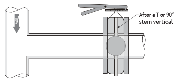
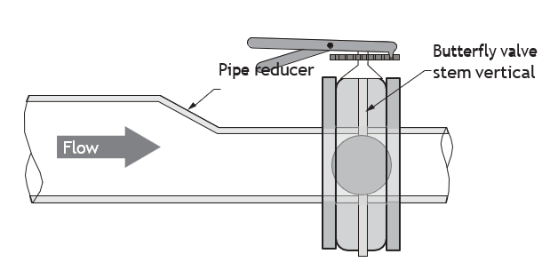
Butterfly valves are typically installed with the stem vertical and with the actuator mounted vertically directly above it. There are some applications where the stem should be horizontal.
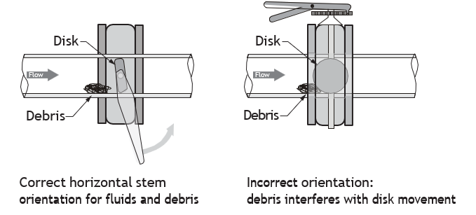
For media with sediment or particles, such as slurries, sludge, mine tailings, pulp, and dry cement, install the valve with the stem horizontal, and the lower disk edge opening toward the downstream direction.
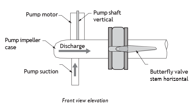
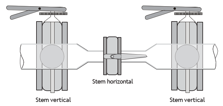
When combinations of butterfly valves are installed close together, there is a possibility of noise, vibration, and erosion due to fluid turbulence. Noise, vibration, and erosion are less likely when the stem of the centre control valve is at a right angle to those of the adjacent valves.
Butterfly Valve Flanged Installation Procedures
- Make sure the pipeline and flange faces are clean. Any foreign material such as metal filings, pipe scale, welding slag, welding rods, etc., can limit disk movement or damage the disk or seat.
- Gaskets are often not required on resilient seated valves because they extend to both faces of the valve. Check the manufacturer’s specifications.
- Align the pipe-work, and spread the flanges enough to allow the valve body to be easily inserted between the flanges without contacting the pipe flanges.
- Check that the valve disk has been set to about 10% open so it does not become jammed in the fully seated position.
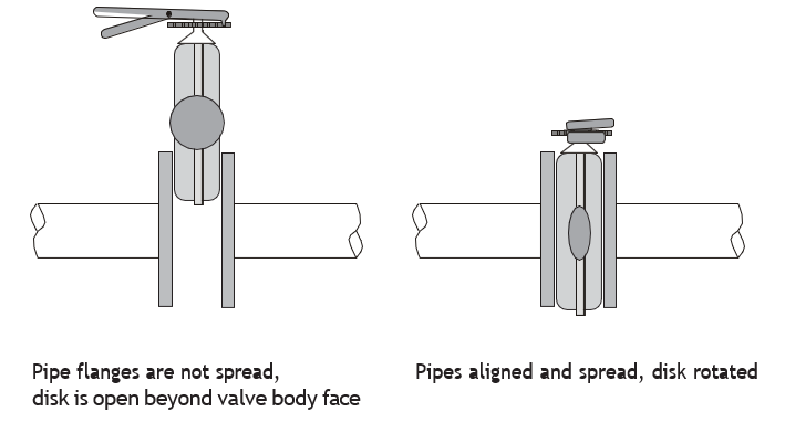
- Insert the valve between the flanges as shown, taking care not to damage the seat faces. Always lift the valve by the locating holes or by using a nylon sling on the neck or the body. Never lift the valve by the actuator or operator mounted on the valve.
- Centre the valve between the flanges, insert the bolts and hand-tighten them. Carefully open the disk, making sure the disk does not contact the inside of the adjacent pipes.
- Very slowly close the valve disk to ensure disk edge clears the adjacent pipe flange.
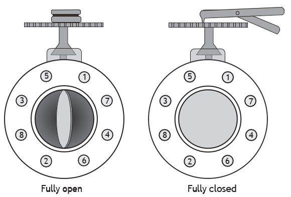
- Fully open the disk and tighten all flange bolts in the order shown in Figure 12.
- Repeat a full close to full open rotation of the disk to ensure proper clearances.
Butterfly Valve Installation with Welded Flanges
When butterfly valves are to be installed between welding-type flanges, take the following measures to ensure the seat is not damaged:
- Place the valve between the flanges with the flanges and valve body aligned. The disk should be 10% open.
- Bolt the flanges to the valve body. Ensure that the valve and flanges are aligned with the pipe.
- Tack-weld the flanges to the pipe.
- Remove the bolts and the valve from the pipe flanges and finish welding the flanges.
- Wait for the pipe and flanges to cool before installing the valve.
Never complete the welding (after tacking) with the valve between flanges because heat transfer will cause severe seat damage.
Temperature and Pressure Relief Valve Installation
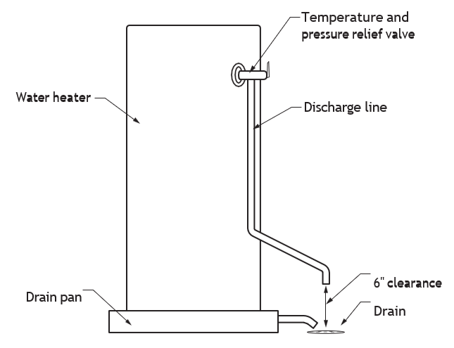
The temperature-sensing element placed in a hot water storage tank so the element is positioned in the water within the top 150 mm (6 in) of the tank. The standard temperature relief setting is 99°C (210°F). Standard pressure setting of a hot water storage heater is 1034 kPa (150 psi).
Pressure relief valve settings for other equipment can vary. It is essential that a discharge line be piped from the valve in order to carry the overflow to a safe place of disposal. The discharge line must be the same size as the valve outlet and must pitch downward from the valve and terminate at least 152 mm (6 in) above the floor drain where any discharge will be clearly visible.
Check with the local regulatory authority for drain installation.
Relief Valve Installation
Always check the manufacturer’s specification for recommendations regarding positioning relief valves. For example, although relief valves are usually installed in the upright position, with the stem vertical, there are exceptions. For air or gas service, relief valves are positioned upside down so that moisture will collect and seal the seating surfaces inside the valve.
Vacuum Relief Installation
A vacuum relief valve must be installed on a hot water storage heater so that it is approximately 150 mm (6 in) above the storage heater tank. The vacuum relief is located on the cold water supply line downstream of any shut-off valves used to isolate the equipment it is protecting. Check with the local regulatory authority for drain installation.
Valve Locations
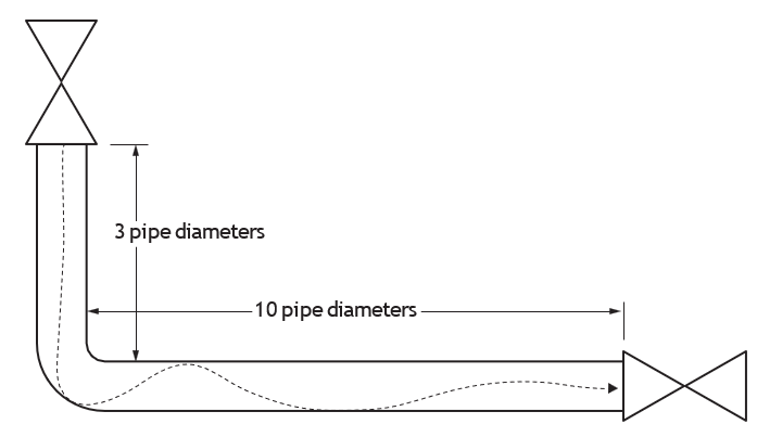
Any sharp change in pipe direction, such as at an elbow or tee, will cause turbulence and pressure loss. To minimize overall turbulence and pressure loss, valves should be installed at a reasonable distance from any sharp bend or turn in piping.
Figure 14 shows a general guide for locating valves away from other fittings. For example, if the pipe has a diameter of 2 inches, then the valve should be located at least 510 mm (20 in) downstream or 152 mm (6 in) upstream from the nearest elbow or tee.
 Self-Test D-2.2: Install Valve
Complete Self-Test 2.2 and check your answers.
If you are using a printed copy, please find Self-Test D-2.2 and Answer Key in the Appendix at the end. If you prefer, you can scan the QR code with your digital device to go directly to the interactive Self-Test.

References
BC Industry Training Authority. (2019). Piping trades apprenticeship program: Use Tools and Equipment—Level 1 harmonized [Binder]. Crown Publications, Queen’s Printer for British Columbia. https://www.crownpub.bc.ca/Product/Details/7960000261_S
- Plumber: Competency D-4 Install Valves
- Steamfitter: Competency D-1 Install Valves
- Sprinkler Fitter: Competency D-4 Install Valves
Media Attributions
All figures are sourced from Industry Training Authority (2019) and/or Camosun College (2019) and are used under the Creative Commons Attribution 4.0 (CC BY 4.0) licence unless otherwise noted. Images copyrighted by the BC Industry Training Authority are licensed under a Creative Commons Attribution-NonCommercial-ShareAlike 4.0 (CC BY-NC-SA 4.0) licence.
The part of a valve that connects the handle or actuator to the internal closing part (such as a disk or gate) and moves to open or close the valve. (Section D-2.1)
A rod inside a valve that connects the handle to the internal parts and turns or moves to open or close the valve. (Section D-2.2)
A type of gate valve that uses a single, solid wedge-shaped gate to close tightly against the valve seats and stop flow. (Section D-2.2)
A check valve with a hinged disk that swings open with forward flow and closes to prevent reverse flow. (Section D-2.1)
A metal pin that allows a valve disk or part to pivot or swing open and closed. (Section D-2.2)
A device that moves a valve open or closed, either by hand or using power such as air, electricity, or hydraulic pressure. (Section D-2.2)