D-1.3 Describe the Methods of Pipe and Tubing Support
Pipe Support
The installation of pipe and piping equipment requires proper support. Pipe support can be accomplished in a number of ways:
- Pipe hangers
- Pipe anchors
- Pipe guides
- Inserts and expansion shields
- Brackets and clamps
- Seismic braces (sway bracing)
- Accessories including sleeves, saddles, and shields
- Pipe slide-plates
Piping support must support the weight of the pipe and equipment, including the contents. Hangers and supports must be designed to accommodate pipe movement from expansion or contraction, as well as vibration seismic activity. The hangers and supports must keep the pipeline in alignment and maintain a specific position related to slope, level, plumb, or any other required design position.
Most piping installations are governed by codes and specifications. For example, requirements for hanger spacing, size, and seismic restraint are stated in various codes, including plumbing codes, fire sprinkler codes, and gas codes. In every case, the maximum allowable spacing of pipe hangers is clearly stated. Regardless of the maximum spacing allowed, when pipe sags, additional support should be added to ensure proper alignment and support. Job site engineered specifications and manufacturers’ instructions should be followed where code regulations are not sufficient.
Pipe hangers and supports can be broadly classified into the following categories:
- Rigid hangers/supports
- Variable effort supports/hangers
- Constant effort supports/hangers
- Spring-loaded sway braces
- Dynamic restraints/rigid struts
- Snubbers/shock absorbers
Code Examples for General Hanger and Support Installation Guidelines
Pipe supports for nominally horizontal piping should be supported and sized as follows:
- Where hangers are used to support nominally horizontal piping they shall be:
- Metal rods of not less than:
- 6 mm diameter to support piping 2″ or less in size
- 8 mm diameter to support piping 4″ or less in size
- 13 mm diameter to support piping over 4″ in size
- Solid or perforated metal straps of not less than:
- 0.6 mm nominal thickness and 12 mm wide to support piping 2″ less in size
- 0.8 mm nominal thickness and 18 mm wide to support piping 4″ or less in size
- Metal rods of not less than:
- Where a hanger is attached to concrete or masonry, it shall be fastened by metal or expansion- type plugs that are inserted or built into the concrete or masonry.
- Underground horizontal piping shall be supported on a base that is firm and continuous under the whole of the pipe.
- Underground horizontal piping that is not supported on a base that is firm and continuous under the whole of the pipe, may be installed using hangers fixed to a foundation or structural slab, provided that the hangers are capable of keeping the pipe in alignment and supporting the weight of the pipe, its contents, and the fill over the pipe.
- Where a vent pipe that may be subject to misalignment terminates above the surface of a roof, it shall be supported or braced.
- Piping shall be provided with support that is capable of keeping the pipe in alignment and bearing the weight of the pipe and its contents.
- Nominally horizontal piping that is inside a building shall be braced to prevent swaying and buckling and to control the effects of thrust.
- The design and installation of every piping system shall include means to accommodate its expansion and contraction caused by temperature changes, movement of the soil, and building shrinkage.
- Where piping is installed underground, the backfill shall be carefully placed and tamped to a height of 300 mm.
- Where asbestos-cement drainage pipe or vitrified clay is located less than 600 mm below a basement floor and the floor is constructed of other than 75 mm or more of concrete, the pipe shall be protected by a 75 mm layer of concrete installed above the pipe.
- Where piping passes through or under a wall, it shall be installed so that the wall does not bear on the pipe.
- Where piping may be exposed to freezing conditions, it shall be protected from the effects of freezing.
- Plumbing, piping, and equipment exposed to mechanical damage shall be protected.
- Piping may need to be protected against condensation.
 Refer to the actual code related to your piping trade. Information not found in the code can be found by consulting the engineer-designed systems or the specific manufacturer’s installation requirements.
Structural Restrictions for Hangers and Supports
The type of hangers and supports chosen will also depend upon the makeup of the building’s structural components. When using “redi-rod” (threaded rod) for hangers within a wood-framed structure, you will undoubtedly require brackets and plates that are secured to the structure using wood screws. Concrete and steel structures, on the other hand, will have support components that are clamped onto steel or drilled into concrete.
Concrete buildings that are post-tensioned usually do not allow drilling into the underside or topside of suspended slabs, so the supports and holes for piping must be cast in place, requiring careful preplanning of piping routes to avoid interference with other trades. Drilling or coring into a post-tensioned structure can be extremely dangerous to anyone in the vicinity, and the associated hazards and prohibitions are normally explained on-site through a first-day orientation session for any workers new to the site.
General Installation Guidelines for Hangers and Supports
For each hanger piping installation, you’ll be required to select and install the appropriate types of hangers and supports. Many factors must be considered when selecting these hangers, supports, and fasteners. General installation guidelines exist. However, you should always refer to the appropriate code requirements, job site specifications, and manufacturer’s instructions.
Selecting Hangers, Supports, and Fasteners
Use the following general guidelines to select, install, and size hangers, supports, and fasteners:
- Refer to job specifications for the correct type of hanger.
- Consider pipe movement such as expansion, contraction, or vibration.
- Establish the type of pipe and the weight of the material and its contents.
- Identify the piping material regarding contact between the hanger and the material the hanger is made of. Contact between dissimilar metals can result in electrolytic action between hangers and piping.
- Consider whether the piping will be insulated.
- Identify the building structure material (e.g., concrete, steel, or wood).
- Select the correct fastener type and installation method. For example, wood screw, lag screw, bolts, or beam clamp.
- Refer to the manufacturer’s maximum load capacity requirements for each hanger and fastener.
- Never exceed the maximum load capacity of the hanger or fastener.
- Refer to the job plans to determine the correct position of each hanger and support. In many cases, a chalk-line or string line can help establish hanger and fastener positions for long pipe line lengths.
- If seismic restraint/sway-bracing is required, determine the correct positioning as stated by governing codes such as the Fire Sprinkler Code.
- Ensure that each hanger is tight to the pipe and supporting the pipe as it should be.
- For vertical piping, ensure vertical riser clamps or similar support is spaced and located as required by the code or job site specifications.
- Select hangers that can be adjusted when adjustment of piping heights is required.
Once you have a general idea of the type and size of hangers, supports, and fasteners you will require, consult the manufacturer’s catalogues for further details. Most catalogues will include detailed sketches of the important dimensions to be considered when selecting each type of hanger.
Types of Pipe Support
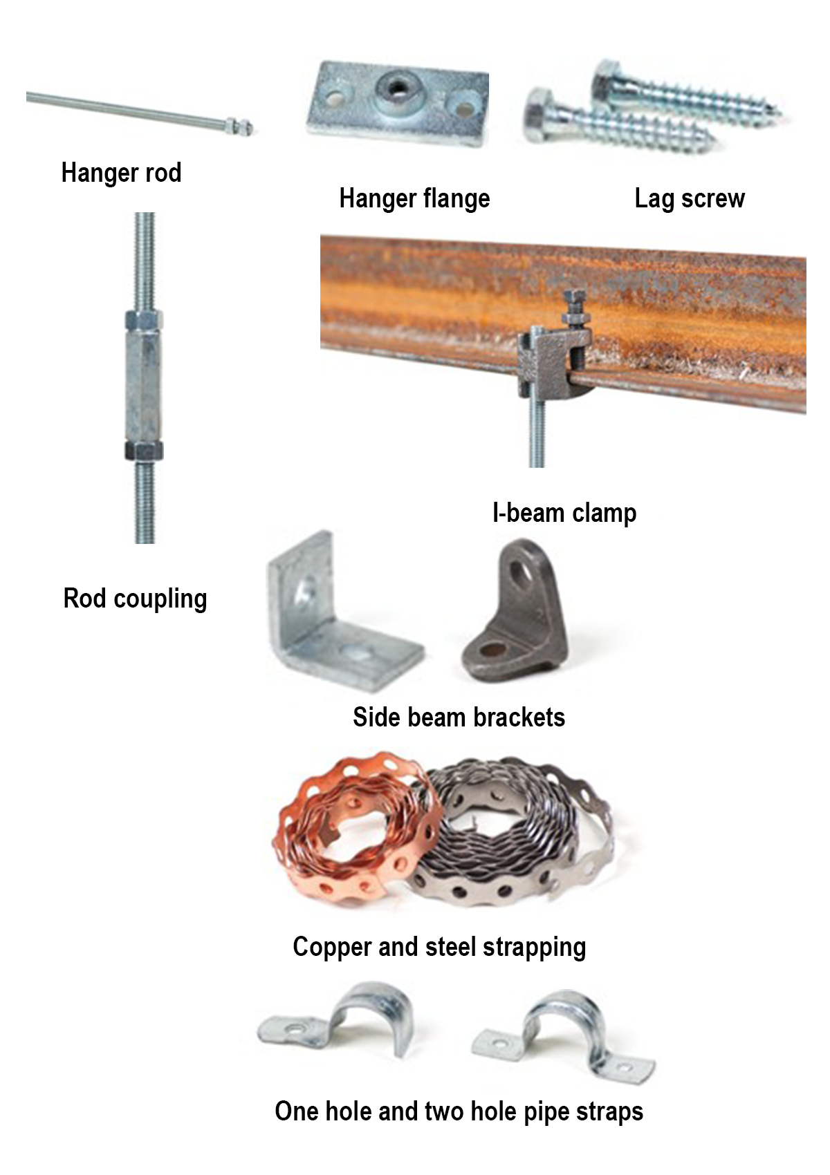
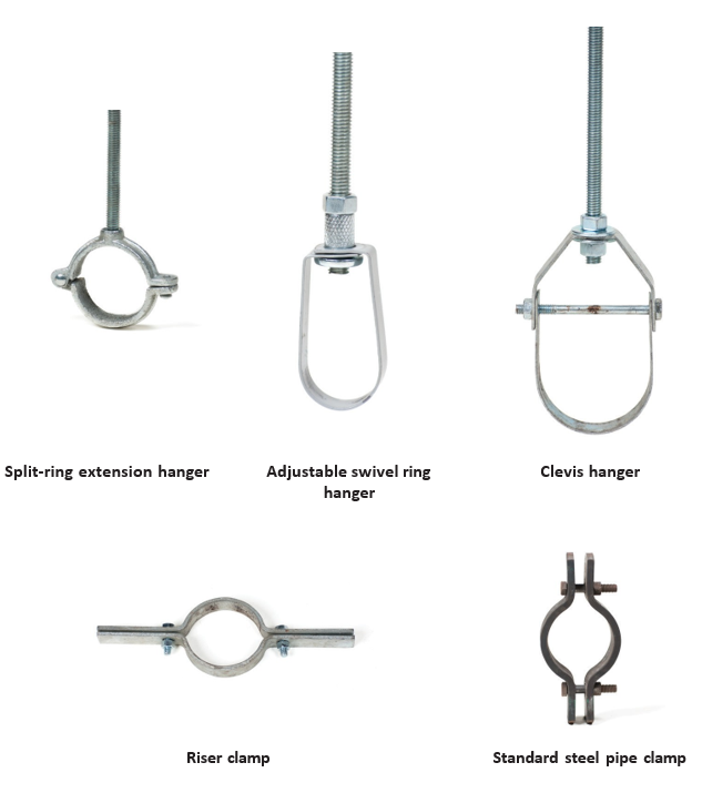
The following images show common types of pipe support.
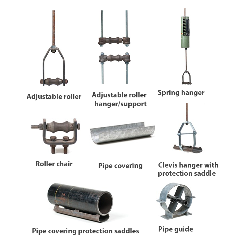
Pipe saddles are used to support the pipe and protect the pipe insulation from being crushed by the pipe hanger. They also provide protection beneath the insulation. Standard lengths for pipe saddles range from 9″ to 12″. Custom radii, gauges, and lengths are available.
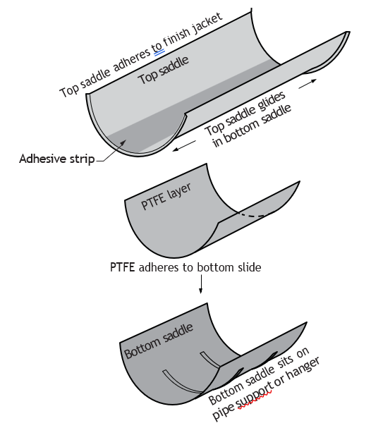
Sliding Pipe Saddle Insulation Protection
A sliding pipe saddle minimizes weather barrier damage caused from pipe movement.
- Inner saddle adheres to the insulation barrier and moves with the piping, while sliding on the PTFE (poly-tetra-fluoro-ethylene) surface below (see Figure 11, component C).
- Ribbed lower saddle remains stationary on the pipe hanger.
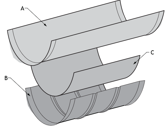
The PTFE layer is laminated to the lower saddle providing a minimal friction surface for the upper saddle to slide against.
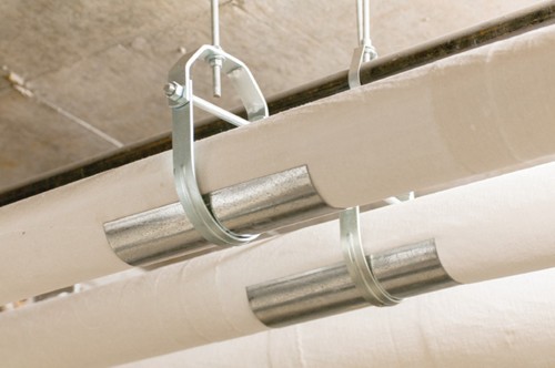
Gliding Pipe Saddles
Figure 12 show the use of a gliding (sliding) pipe saddle on a large insulated exterior pipe line. The saddle allows the pipe to expand and contract easily over the pipe supports. This saddle reduces or eliminates damage to the pipe jacketing and the vapour barrier under it.
Pipe Anchors
Pipe anchors are used to secure piping systems and prevent unwanted movement. Engineer specifications governing codes and manufacturers’ instructions will dictate the correct use of pipe anchors. Various thread type and diameter sizes are available. Pre-drilling holes of the correct size is required before installation to insert the anchors. The required drill bit sizes are specified by the manufacturer’s packaged instructions.
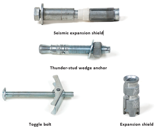
The following images show equipment for anchoring pipe.
Drop-in Anchor
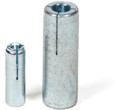
The steel drop-in is a machine bolt anchor available zinc plated carbon steel in bolt sizes [latex]\frac{1}{4}[/latex] – [latex]\frac{3}{4} \text{"}[/latex]. It can be used in solid concrete, hard stone (granite), and solid block. A hand setting tool is required.
Applications and uses of pipe anchors:
- Pipe hanger support
- Suspending conduit and lighting, cable trays and strut, and concrete formwork
- Can be installed flush-mounted or below the base material surface
Concrete drop-in anchor installation:
- Confirm the location for the insert to be installed to ensure you’re not drilling into concrete that has encased electrical or other components.
- Drill hole into the concrete with a carbide tipped masonry drill matching the bit size with the outside diameter of the drop-in anchor being used. Check the hole for the correct depth.
- Clean out concrete dust from the hole using a wire brush, compressed air, or a blowout bulb.
- Thread the bolt into the anchor. Drive the anchor into the hole, flush with the surface of the concrete. Remove bolt.
- Using the proper setting tool for the anchor, expand the anchor by inserting the setting tool into the anchor and setting it with several solid hammer blows. The anchor is set properly when shoulder of the setting tool is flush with the top of the anchor.
- To set the anchor below the surface, drill the hole deeper than the anchor length. Thread the bolt into the anchor. Hammer the anchor into the hole until the bolt head is the desired depth. Remove the bolt and set the anchor with the setting tool, as described above.

Drop-In Concrete Anchor Spacing
As a general rule, the expansion industry has established a minimum standard of ten anchor diameters for spacing between anchors and five anchor diameters from an unsupported edge. When vibration or sudden impact is part of the load condition, spacing between anchors should be increased.
Expansion Anchors
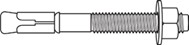
Expansion anchors, sometimes referred to as quick-bolts are threaded fastener studs, with specially formed ends, used to attach machinery components to concrete. A specifically sized hole is drilled into a concrete slab, and an anchor with its split collar is gently tapped into the hole. As the nut tightens onto the material that the bolt is meant to fasten to the concrete, the natural tendency is to pull the bolt back out of the hole. However, the split collar binds between the sides of the concrete hole and the tapered end of the bolt, causing the bolt/collar to bind and hold fast. Once the bolt/collar combination is embedded, it will not be possible to extract it, and it must be cut off using an angle grinder if removal is necessary. The use of a quick-bolt eliminates the need for a concrete anchor and threaded rod combination.
Expansion Inserts
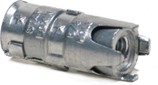
The single expansion insert is a single-action machine bolt expansion anchor. It can be used in solid concrete, hard stone (granite), and solid block and brick.
General applications and uses:
- Pipe hangers
- Suspending conduit and lighting
- Cable trays and strut
Single expansion insert installation:
- Confirm the location for the insert to be installed to ensure that you’re not drilling into concrete that has encased electrical or other components.
- Drill a hole using a carbide tip drill bit of the manufacturer-recommended diameter. The depth should be equal to, or slightly deeper than, the length of the expansion shield (anchor).
- Clean out the hole of all dust and cuttings.
- Place the single expansion insert, nut end first, into the hole. The top end of the anchor should be flush or slightly below the base material surface.
- Place the object to be fastened over the anchor in the base material and bolt it into place. The bolt should engage [latex]\frac{2}{3}[/latex] of the threads of the anchor.
Precast Insert Hanger Anchors
The cast-in place insert is designed for pre-planned fastening in concrete. The insert provides rustproof threaded metal inserts in precast, pre-stressed or poured-in-place concrete. Install with bolts through holes in steel forms or by means of reusable concrete insert plugs on wood forms.
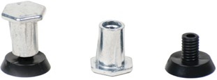
Pre-cast anchor applications:
- Heavy machinery
- Pipe hangers support
- Duct work
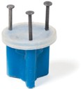
Figure 20 Wood form cast-in-place insert (BC Industry Training Authority, 2019). CC BY-NC-SA 4.0
Wood Form Cast-in-place Insert
The wood form concrete insert is installed onto wooden forms used to support newly poured concrete floor slabs, roof slabs, or walls. Refer to D-4 Penetrate Structures for information on use of this type of insert. The six-sided impact plate offers resistance to rotation within the concrete as the threaded rod is being installed.
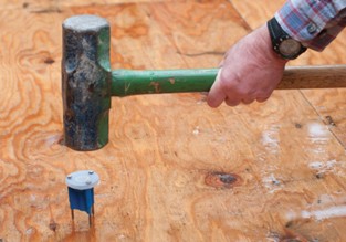
Wood form cast in-place insert applications and uses:
- Hanging pipe and sprinkler systems
- Overhead utilities
- HVAC ductwork
- Strut channels
Roof Deck Insert
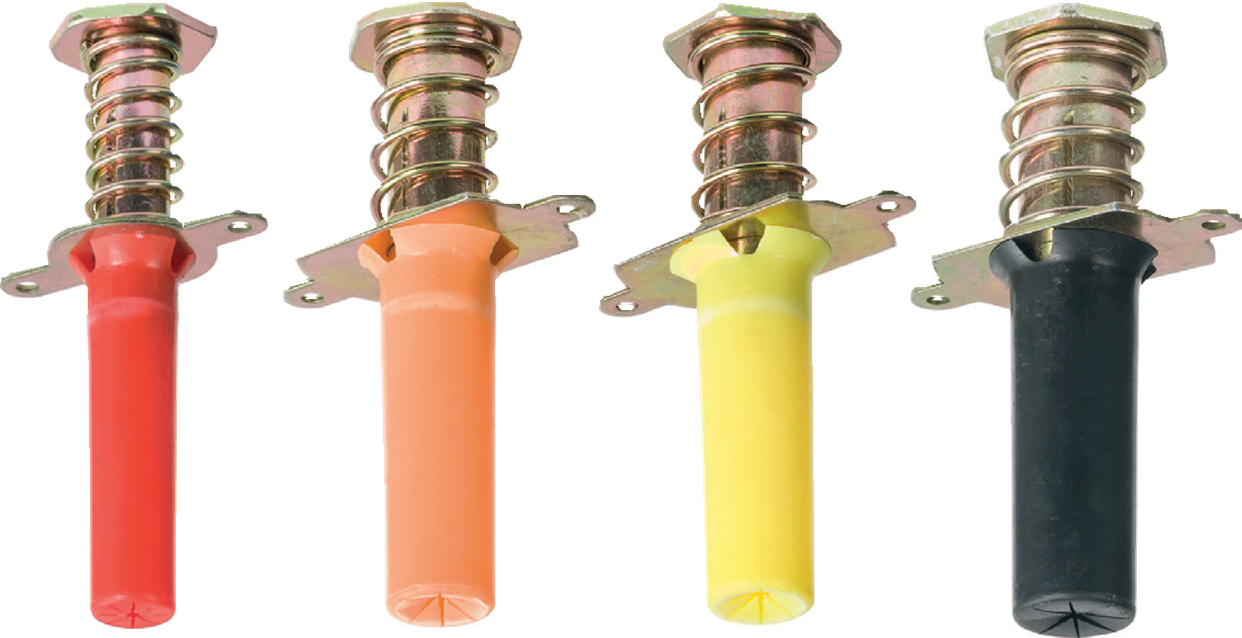
Metal deck insert anchors are designed for installation through the pre-drilled metal composite deck used to support a newly poured concrete floor or roof slab. Depending upon the size chosen, the protective sleeve protrudes below the surface of the deck, allowing overhead attachment of threaded rod or bolts.
Roof deck insert applications and uses:
- Hanging pipe and sprinkler systems
- Overhead utilities
- HVAC ductwork
- Strut channels
Rod Hangers
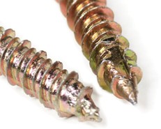
A rod hanger is an all-steel threaded anchor system for suspending threaded rod. These hangers can be used in a variety of base materials, including poured concrete, steel joists and beams, and wood frame columns and beams. Drill bits and installation tools are required as per manufacturer’s specifications. (For example, carbide bits are required for drilling concrete.) Rod hangers have several other common names: hang-up anchors, Sammy super screws, vertigo anchors, hanger mates, and titan anchors.
Rod hanger applications and uses:
- Hanging pipe and sprinkler systems
- Lighting systems, suspended ceilings
- Suspended conduit and cable trays
- HVAC ductwork and strut channels
- Mounting security equipment
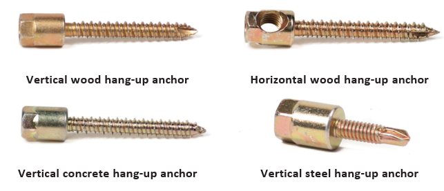
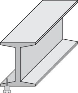
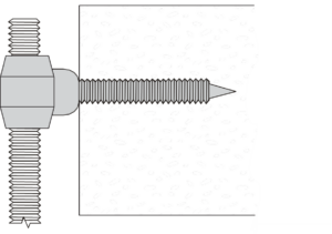
Rod Hanger Installation
- Drill a hole into the base material using the drill bit provided with the screws. The hole must be at least [latex]\frac{1}{4} \text{"}[/latex] deeper than the anchor embedment.
- Place the object to be fastened over the hole.
- Insert the point of the anchor into the hole and drive the screw in using a nut drive or number 3 bit tip. Do not over-torque the screw.
Light-duty and Hollow Wall Anchors
Light-duty and hollow wall anchors have restricted use for supporting pipe and heavy equipment. In most cases, these anchors do not have the holding power of expansion or drop-in hangers. In the piping trade, these anchors can be used only for light-duty applications such as mounting light-weight components. They can be used in concrete, block, tile, wallboard and brick with a sheet metal, wood or lag screw.
Applications and uses:
- Mounting accessories such as control boxes or towel racks
- Attaching light-weight, small diameter piping to hollow block walls
- Wiring and similar attachments
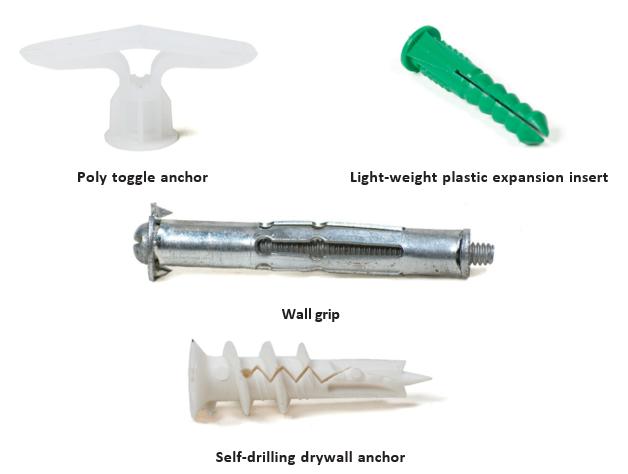
Self-Drilling Drywall Anchor Installation
- Insert a Phillips screwdriver into head of the anchor.
- Press the point of the anchor into the wallboard, while turning the anchor clockwise until it is seated flush with the wall.
- Place the fixture over the hole and tighten the proper size sheet metal screw. A minimum thread engagement of 1″ is recommended.
Residential Hanger Attachment Methods
Strap iron (often called plumber’s tape or metal hanger strap) is a thin, flexible strip of metal (typically galvanized steel), used in plumbing to support and secure piping systems. It usually comes in rolls or flat lengths and features pre-punched holes along its length, allowing it to be easily fastened with screws, nails, or bolts. Strap iron is commonly used in residential and commercial plumbing installations where pipes need to be suspended, stabilized, or restrained.
Shown below are several methods of pipe support used in wood-frame buildings.
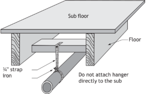
The Plumbing Code will designate the correct size and gauge of strap iron.
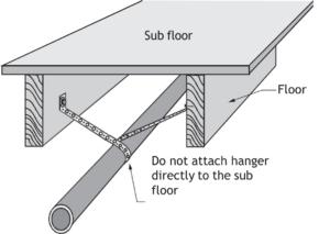
Although the method shown in Figure 29 is acceptable, it requires more strap iron than in the method shown in Figure 28.
Note: When using hanger strap iron to support piping in drop ceilings and crawl spaces, cross bracing is required to prevent the pipe from swaying.
Sometimes wood blocking is used to support the piping when the piping is located within the joist space, as shown in Figure 30.
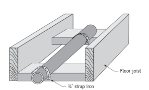
 Hanger supports on residential applications of wood-frame construction are commonly applied with perforated hanger strap. This method is less expensive than using manufactured hanger supports. This strapping allows for flexibility in design of the support. The metal hanger strap installation must be capable of supporting the pipe and holding it in position.
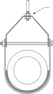
Clevis Hanger with Double Nuts
Figure 31 shows a clevis type hanger with double nuts used on the hanger rod. The purpose of the double nuts is to reduce any swinging motion by holding the pipe more rigidly and reducing the tendency for vibration to loosen the nuts supporting the hanger.
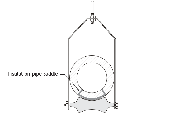
The steel pipe saddle provides a solid surface for the pipe to move on the rollers without damaging the insulation.
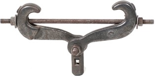
Scissor Beam Clamp
A scissor beam clamp (Figure 33) is used to create a temporary overhead anchor point on steel beams for lifting and rigging applications, such as attaching hoists, lighting rigs, or pipework. It gets its name from the “scissor” action used to clamp onto the beam’s flanges, where twisting a spigot secures the clamp. This method allows for non-permanent installation, which avoids weakening the beam, and is ideal for lifting, construction, and industrial maintenance.
Expansion and Contraction of Hangers and Supports
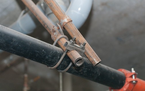
The movement and shifting of suspended pipe can cause damage or failure if not properly controlled. Detailed below are several methods for achieving this control.
- Sway braces are used to restrain pipe movement.
- A spring sway brace allows controlled movement and returns the pipe to its original position.
- A hydraulic shock arrestor protects piping from sudden forces such as water hammer or seismic activity.
Sway Braces
Sway braces are used for controlling and restraining pipe movement, as shown in Figure 34.
Spring Sway Brace
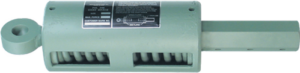
A spring sway brace is a special type of variable effort restraint and is built around a standard or non-standard spring. It’s used to restrain piping or equipment but is not intended to support. A swing sway brace has a pre-loaded spring, which allows both compression and extension movements of the pipe. By installing a spring sway brace, the pipe’s position can move to accommodate forces acting upon it, then return to its neutral position once those forces have stopped.
Hydraulic Shock Arrestor and Sway Suppressors
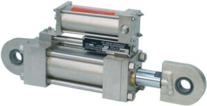
The hydraulic shock arrestor protects pipelines and equipment from the effect of shock loads caused by wind loads, pipe bursts, seismic activity, water hammer, and other sudden forces. When subjected to sudden movements, the shock arrestor “locks” momentarily and forms a rigid connection.
Spring and Variable Supports
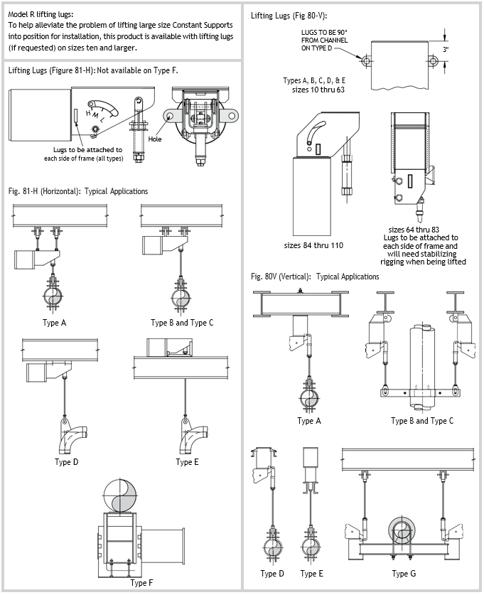
Spring supports are used to support piping and related components that are subject to thermal expansion. For minor vertical travel, a variable spring support (Figure 37) is typically used for relatively small displacements (up to about 75 mm). A constant spring support should be used for greater levels of thermal expansion (Figure 38).
The constant spring supports provide continuous support throughout the total movement of the pipe.
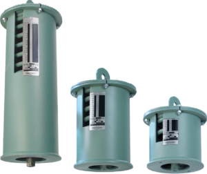
Constant spring supports provide continuous support along the total travel of the pipe.
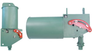
The constant spring support is designed and manufactured based on the principle of a compression spring working in conjunction with a bell crank lever, which balances the spring and load movements, resulting in a constant supporting effort throughout all pipe movement.
Slide Plates
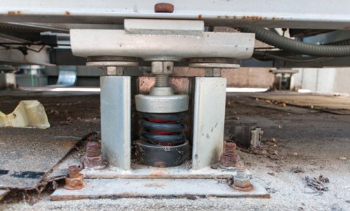
Slide plates are used to provide a surface with a low coefficient of friction so that it can be attached to a supporting structure. The slide plate provides support while allowing the supported equipment to move freely. Slides plates can consist of an upper slide plate and a lower slide plate component that work together as a unit. They can be manufactured for a variety of applications, including the support of piping, heavy equipment such as pressure vessels, and structural steel members.
Seismic Restraint of Mechanical, Electrical, and Plumbing Systems
During an earthquake, the shaking and rolling of the ground is transmitted to the building. The piping and equipment supported by the building’s structure will be adversely affected by this movement. Unrestrained piping and equipment can rip apart, fail, or break loose. Fires, explosions, and flooding are common during earthquakes due to ruptured gas lines, fire sprinkler systems, and plumbing systems. As a tradesperson, you’re responsible for the correct placement and installation of seismic restraints.
Seismic restraint refers to the components and systems used to keep mechanical, electrical, and plumbing systems secured in place while allowing movement with the building’s structure. The goal is to maintain system operation during seismic activity, or at least until the structure itself fails.
Seismic Engineering Specification and Code Requirements
Building codes, plumbing codes, gas codes, and fire sprinkler codes all deal with support and seismic regulations. The Fire Sprinkler Code has extensive requirements for the installation and positioning of seismic restraints. Currently, plumbing and gas codes have more limited specific requirements. Where engineered systems are used, engineering practices and specifications must also be followed.
Basic seismic installation guidelines:
- Conform to Building Code requirements.
- Follow engineered job specifications.
- Follow manufacturer installation instructions.
- In the absence of regulations, follow proven trade practices.
- In all cases, check with the authority having jurisdiction (AHJ).
Guidelines for seismic restraint:
- The seismic restraints’ positions should be coordinated so as not to interfere with each other or the positing of building equipment and structural components.
- Seismic restraint attachments to the building structure must always be strong enough to carry the imposed loading by the piping during seismic activity.
Seismic Supports for Piping Systems and Equipment
Beam Clamp with Strap
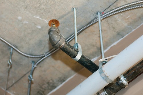
A beam clamp with a restraint strap or safety strap prevents the clamp from walking (slipping) off the beam during seismic events. Restraint straps are required for sprinkler installations in all seismic regions.
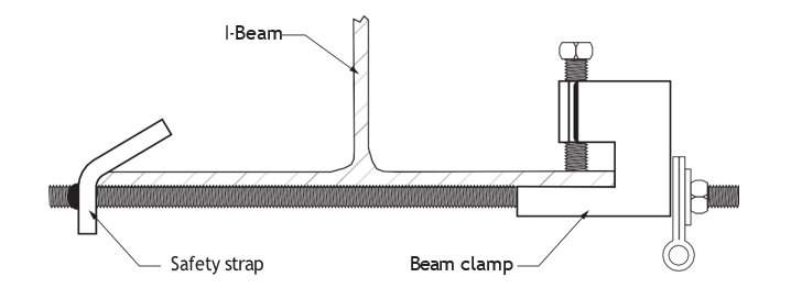
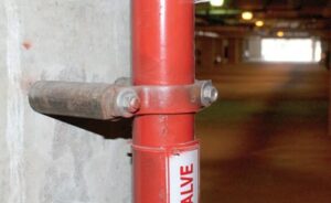
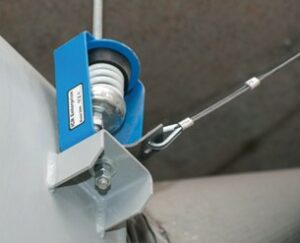
Figures 42–44 show acceptable ways and means of installing seismic attachments. It’s important to note that engineered specifications, Code requirements, and manufacturer instructions must be adhered to.
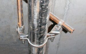
The hangers are close together so that each section of pipe is supported.
Cable-Brace Attachment
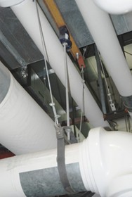
Cable-brace attachments must be installed in a straight line between attachment points and must not bend or wrap around other components (Figure 46).
Power-actuated or power-driven fasteners, such as powder shot pins, must not be used for tensile load applications unless specifically approved for seismic use.
Proper attachment of the mechanical, electrical, and plumbing system components and their seismic restraints is important in order to maintain the building’s functionality following an earthquake. It’s your responsibility to ensure that seismic components, supports and restraints have been properly installed.
Seismic Restraint Components
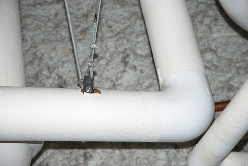
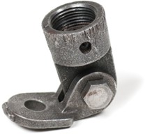
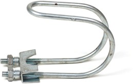
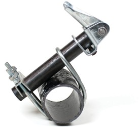
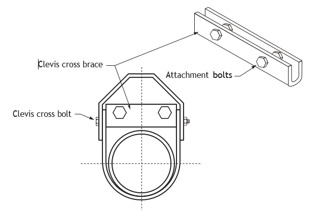
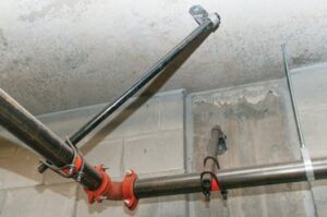
The following components are commonly used to support and anchor pipes (Figures 48–52):
- Sway brace
- U-clamp
- Clevis bracket
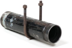
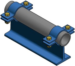
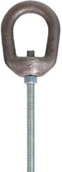
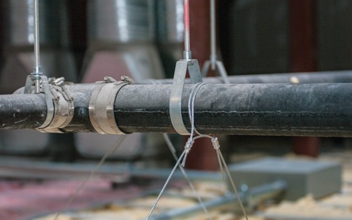
Pipe Support and Anchor Accessories
The following images show accessories used in supporting and anchoring pipes.

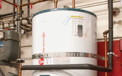
Seismic Bracing of Water Storage Heaters
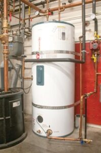
Suggested guidelines for hot water storage heaters:
- Consult the authority having jurisdiction (AHJ) for any local requirements.
- Secure both the top and bottom of the hot water storage heater using heavy-gauge metal strapping.
- Position the tank so that there is approximately 25–50 mm (1–2 in) between the water heater and the wall. If the distance is greater than 50 mm, attach a wooden block to the wall studs with long lag screws to prevent the heater from sliding backwards.
- Wrap heavy-gauge metal strapping 1[latex]\frac{1}{2} \text{"}[/latex] times around the tank:
- Start by placing the strapping at the back of the tank.
- Bring it to the front and then take it back to the wall.
- Secure this strapping to the wall studs or the wood block using longer lag screws with oversized washers. (If securing into concrete, use expansion bolts.)
- Replace all copper and metal piping with flexible natural gas and water line connectors.
- The gas and water lines should have flexible pipes—these may be safer than rigid pipes during an earthquake.
- Remind the customer to check the straps regularly for tightness.
Residential Applications of Pipe Support
You are responsible for designing simple methods to provide adequate support and seismic restraint where possible. The Building Code does not specifically address every situation that occurs on a job site. You need to consider the effects of wood shrinkage and final settlement over time as the structure ages, particularly for wood-frame structures.
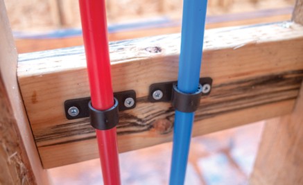
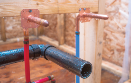
Figure 63 shows the use of strap iron to support the ABS trap arm.
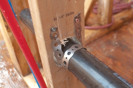
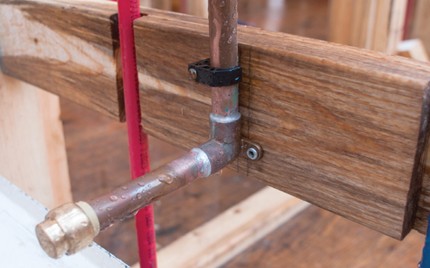
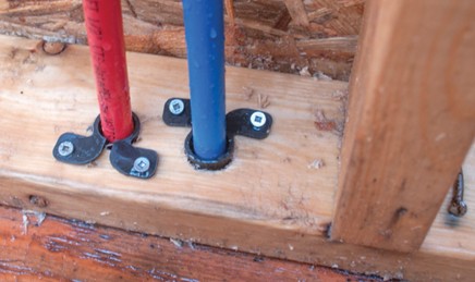
Figure 65 shows the use of plastic clips and grommets. The plastic grommet protects the pipe from contact with the sharp edges of the metal stud framing. Avoiding contact between dissimilar metals is important to prevent galvanic corrosion that can occur in the presence of moisture.
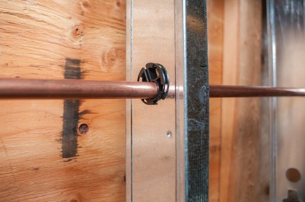
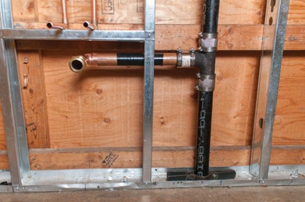
Figure 66 shows the use of plastic tape wrap to isolate the copper trap arm from the dissimilar steel stud. Also shown is the use of a rise clamp to support the vertical cast iron soil pipe.
Hangers and supports guidelines for ABS piping:
- Hangers and straps shall not compress, distort, cut, or abrade the piping and shall allow free movement of pipe.
- Pipe exposed to damage by sharp surfaces shall be protected.
- Support all ABS piping at intervals of not more than 4′ (1219 mm), at end of branches, and at change of direction or elevation.
- Supports shall allow free movement but shall restrict upward movement of lateral runs so as not to create reverse grade.
- Vertical piping shall be supported at each storey or floor level.
- Alignment of vertical piping shall be maintained between floors with the use of a mid-storey guide.
- Support trap arms in excess of 3′ (914 mm) in length as close as possible to the trap.
- Water closet rings shall be securely fastened with corrosive resistant fasteners to the floor with the top surface [latex]\frac{1}{4} \text{"}[/latex] (6.4 mm) above the finished floor.
 Self-Test D-1.3: Describe the Methods of Pipe and Tubing Support
Complete Self-Test 1.3 and check your answers.
If you are using a printed copy, please find Self-Test D-1.3 and Answer Key in the Appendix at the end. If you prefer, you can scan the QR code with your digital device to go directly to the interactive Self-Test.

References
BC Industry Training Authority. (2019). Piping trades apprenticeship program: Use Tools and Equipment—Level 1 harmonized [Binder]. Crown Publications, Queen’s Printer for British Columbia. https://www.crownpub.bc.ca/Product/Details/7960000261_S
- Plumber: Competency D-1 Prepare Pipe
- Steamfitter: Competency D-4 Layout and Install Piping and Tubing
- Sprinkler Fitter: Competency D-1 Prepare Pipe and Tubing
Government of British Columbia. (2025). BC building code 2024. https://www2.gov.bc.ca/gov/content/industry/construction-industry/building-codes-standards/bc-codes/2024-bc-codes
Government of British Columbia. (2025, September 5). BC codes. https://www2.gov.bc.ca/gov/content/industry/construction-industry/building-codes-standards/bc-codes
Government of British Columbia. (2025, June 9). BC fire code. https://www2.gov.bc.ca/gov/content/industry/construction-industry/building-codes-standards/bc-codes/fire
Government of British Columbia. (2025, June 10). BC plumbing code 2024. https://www2.gov.bc.ca/gov/content/industry/construction-industry/building-codes-standards/bc-codes/2024-bc-codes/plumbing
National Fire Protection Association. (2025). NFPA 13: Standard for the installation of sprinkler systems. https://www.nfpa.org/codes-and-standards/nfpa-13-standard-development/13
Media Attributions
All figures are sourced from Industry Training Authority (2019) and/or Camosun College (2019) and are used under the Creative Commons Attribution 4.0 (CC BY 4.0) licence unless otherwise noted. Images copyrighted by the BC Industry Training Authority are licensed under a Creative Commons Attribution-NonCommercial-ShareAlike 4.0 (CC BY-NC-SA 4.0) licence.
A system used to keep pipes and equipment secure during an earthquake. (Section D-1.3)
Concrete that has steel cables inside it to make it stronger. (Section D-1.3)
A reaction between different metals that can cause corrosion when they touch. (Section D-1.3)
A smooth plastic material that reduces friction and allows parts to slide easily. (Section D-1.3)
Devices used to hold pipes firmly in place and prevent movement. (Section D-1.3)
Fasteners that expand inside a hole to hold objects securely in place. (Section D-1.3)
A threaded metal support used to hang pipes from a structure; other common names: hang-up anchors, Sammy super screws, vertigo anchors, hanger mates, and titan anchors. (Section D-1.3)
A thin strip of metal used to support and secure pipes. (Section D-1.3)
A type of pipe support that uses a U-shaped metal bracket and pin to hold and suspend a pipe from above. (Section D-1.3)
A temporary clamp that grips onto a steel beam using a scissor-like action to create a secure attachment point for lifting or supporting equipment. (Section D-1.3)
A support that prevents pipes from moving side to side. (Section D-1.3)
A support that controls pipe movement while allowing limited motion using a spring, helping the pipe return to its original position. (Section D-1.3)
A device that protects pipes from sudden pressure changes, such as water hammer. (Section D-1.3)
Movement of the ground caused by an earthquake. (Section D-1.3)
A pressure surge or high-pressure shockwave that occurs when water in motion is forced to stop or change direction suddenly. It produces a distinct banging or hammering sound, caused by the shockwave traveling back through the pipe. This effect can damage pipes, joints, and appliances. (Section D-1.3)
A support that allows pipes to move up and down while still holding their weight. (Section D-1.3)
The increase in size of a material when it is heated. (Section D-1.3)
A pipe support that uses a spring to carry the load, where the supporting force changes slightly as the pipe moves. (Section D-1.3)
A pipe support that uses a spring mechanism to provide the same supporting force even as the pipe moves. (Section D-1.3)
A mechanical device that helps change the direction of movement and balance loads. (Section D-1.3)
Flat surfaces that support equipment while allowing it to move easily. (Section D-1.3)
A measure of how easily one surface slides over another. (Section D-1.3)
A device used to attach piping or supports to a steel beam without drilling, by gripping the beam securely. (Section D-1.3)
A support system that uses tensioned cables to hold piping in place and resist movement, especially during seismic activity. (Section D-1.3)
Fasteners that are driven into materials like concrete or steel using a tool powered by explosive charges or compressed force. (Section D-1.3)
Metal pins driven into hard materials using a powder-actuated tool, often used for quick fastening into concrete or steel. (Section D-1.3)
Situations where a fastener or support must hold forces that are pulling or stretching it apart. (Section D-1.3)
Organizations or officials (such as inspectors) who enforce codes and regulations and approve whether work meets required standards. (Section D-1.1)
Damage that occurs when different metals touch and react in the presence of moisture. (Section D-1.3)