D-1.2 Describe the Methods of Manufacture of Piping and Tubing
This section introduces the materials and manufacturing methods used to produce common piping and tubing in the trades. You will learn how pipes are made from carbon and stainless steel, cast iron, copper, and thermoplastic materials, and how these processes affect their strength, durability, and use. The section also explains how to identify different types of copper tubing, including their colour markings, and defines the term “temper” as it applies to copper. In addition, you will explore the three main methods used to manufacture cross-linked polyethylene (PEX) tubing, helping you understand how material properties relate to real-world applications in plumbing systems.
Carbon Steel Pipe
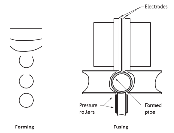
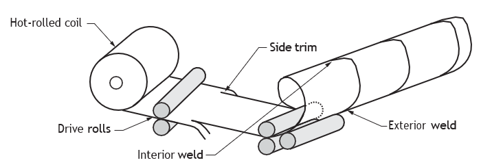
Schedule steel pipe and tube are types of steel pipe. Both are made from mild carbon steel and undergo similar manufacturing processes, in which strips of steel are passed through rollers until they form the desired shape. Then the seam is electrically welded. This process is shown in Figure 1. The tube is rolled at a high temperature, while the pipe is cold-rolled. Both tubing and pipe can be galvanized to protect them from corrosion.
The standard methods of manufacturing steel pipe are:
- Butt weld
- Electric resistance weld
- Seamless pipe
- Spiral weld pipe
Electric Resistance Weld
The processing of electric-resistance welded pipe (ERW) starts with coiled ribbon of steel plate called a skelp. The ribbon is pulled through a series of rollers, which gradually form it into a cylindrical tube. As the edges of the plate come together, an electric charge is applied, heating the edges so they can be welded together. Electric resistance welded pipe is a high-speed production product that can be made in continuous lengths over 100 ft long.
Typically for light construction purposes, the ERW pipe is approximately 6.4 m (21 ft) long, plus or minus 25.4 mm (1 in).
Pipe can be ordered with end finishes. For example, it can be:
- Threaded and coupled
- Threaded without couplings
- Plain end
- Bevelled for welding
- With grooved ends
- Special order
 You can also refer to IPT’s Pipe Trades Handbook and Manual for an image of the electric resistance weld.
Seamless Steel Pipe Manufacturing
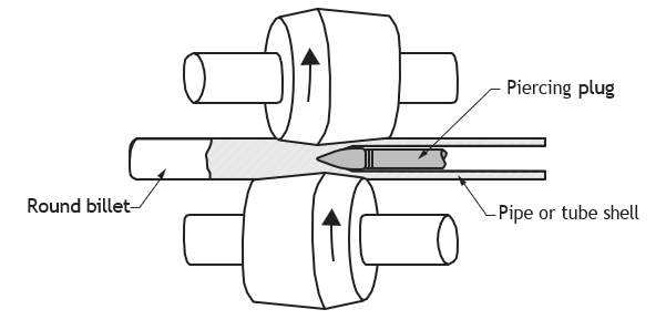
Seamless pipe is made when steel in a solid, cylindrical shape, called a billet or a tube round, is heated and then either pushed or pulled (while being rapidly rotated) over a mandrel with a piercing point positioned in the centre. This produces a hollow tube or “shell.” The tube is then further finished until it becomes the desired size and wall thickness. Since the pipe is formed while heated, it is normalized and has a consistent steel cellular pattern (or microstructure) throughout its circumference.
Seamless pipe is made in sizes from [latex]\frac{1}{8}[/latex]–26″ and is widely used in the construction, oil refining, chemical, and petro-chemical industries.
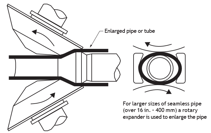
For larger sizes of seamless pipe (over 16 in – 400 mm) a rotary expander is used to enlarge the pipe.
Fusion Welding Process
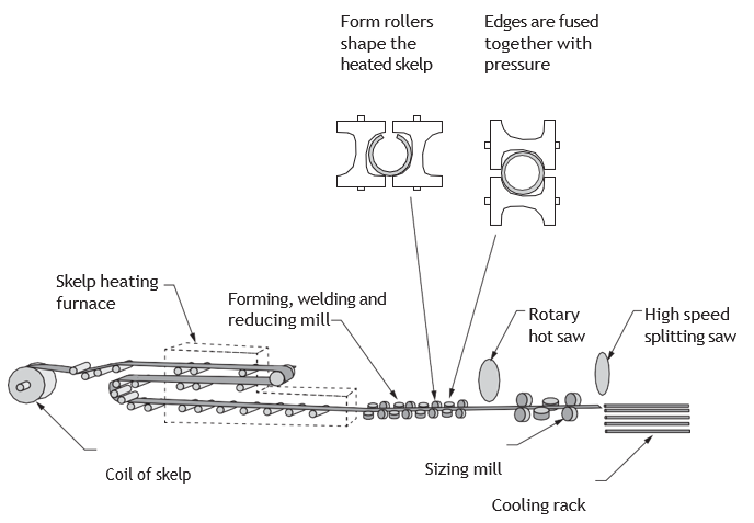
Another process for producing pipe is fusion welding (sometimes called “continuous weld”) and is produced in sizes [latex]\frac{1}{84.5} \text{"}[/latex]. Fusion-weld pipe begins as coiled steel ribbon (skelp). Successive coils of steel are welded end-to-end to form a continuous ribbon of steel. The ribbon of steel is then flattened and straightened and then fed into a gas furnace, where it’s heated to the required temperature for forming and fusing. Forming rollers at the end of the furnace shape the heated skelp into an oval. The edges of the skelp are then firmly pressed together by the rollers, fusing the steel and creating a forged weld. Final sizing rollers form the pipe to its required dimensions.
Spiral-welding Process
Spiral-weld pipe is a steel pipe with a double submerged arc weld (DSAW) seam in a spiral form along the entire length of the pipe. This process allows for large-diameter pipe production. The outside diameter is determined by the angle of the de-coiled steel against the forming machine head. The more acute the angle, the greater the diameter. The production of large, hot-rolled coils of sufficient width and the development of dependable non-destructive testing methods has enabled this product to be placed in more demanding service. Spiral-weld pipe can be rolled in exact lengths up to 115 feet in either ID or OD dimensions up to 144 inches. There is a minimum tonnage required for rolling. Because the manufacturing process is slow, it gives the contractor an advantage of short term changes to the order. This same slow production can also be a disadvantage when large tonnages are needed with a short lead time. Spiral-weld pipe is produced to limited specifications.
Double Submerged Arc Weld Process
Submerged arc welded (SAW) pipe derives its name from the process wherein the welding arc is submerged in flux while the welding takes place. The flux protects the steel in the weld area from any impurities or contaminants in the air when heated to welding temperatures. When both inside welds and outside welds are performed, the welding is accomplished in separate processes and the pipe is considered to be double submerged arc welded (DSAW) pipe.
There are three common types of pipe produced by the DSAW process.
- U&O process
- Rolled
- Spiral-weld
U&O Process
The U&O process uses a “U” press, then an “O” press to form a complete cylinder from 40′ long steel plates. The cylinder is then welded inside and outside by the submerged arc process by using as many as five welding wires. The primary use of this type of large pipe is gas and oil transmission fields.
Rolled and Welded Process
The rolled and welded method of manufacturing is also called the pyramid roll method because it uses three rolls arranged in a pyramidal structure. The steel plate is rolled back and forth between the pyramid rolls until the cylinder is formed. The cylinder is then moved to the welding stations. Most pyramid rolls are 20′ long or less. Greater lengths can be ordered. This process can produce large pipe diameters, either ID or OD.
Cast Iron Pipe and Fittings
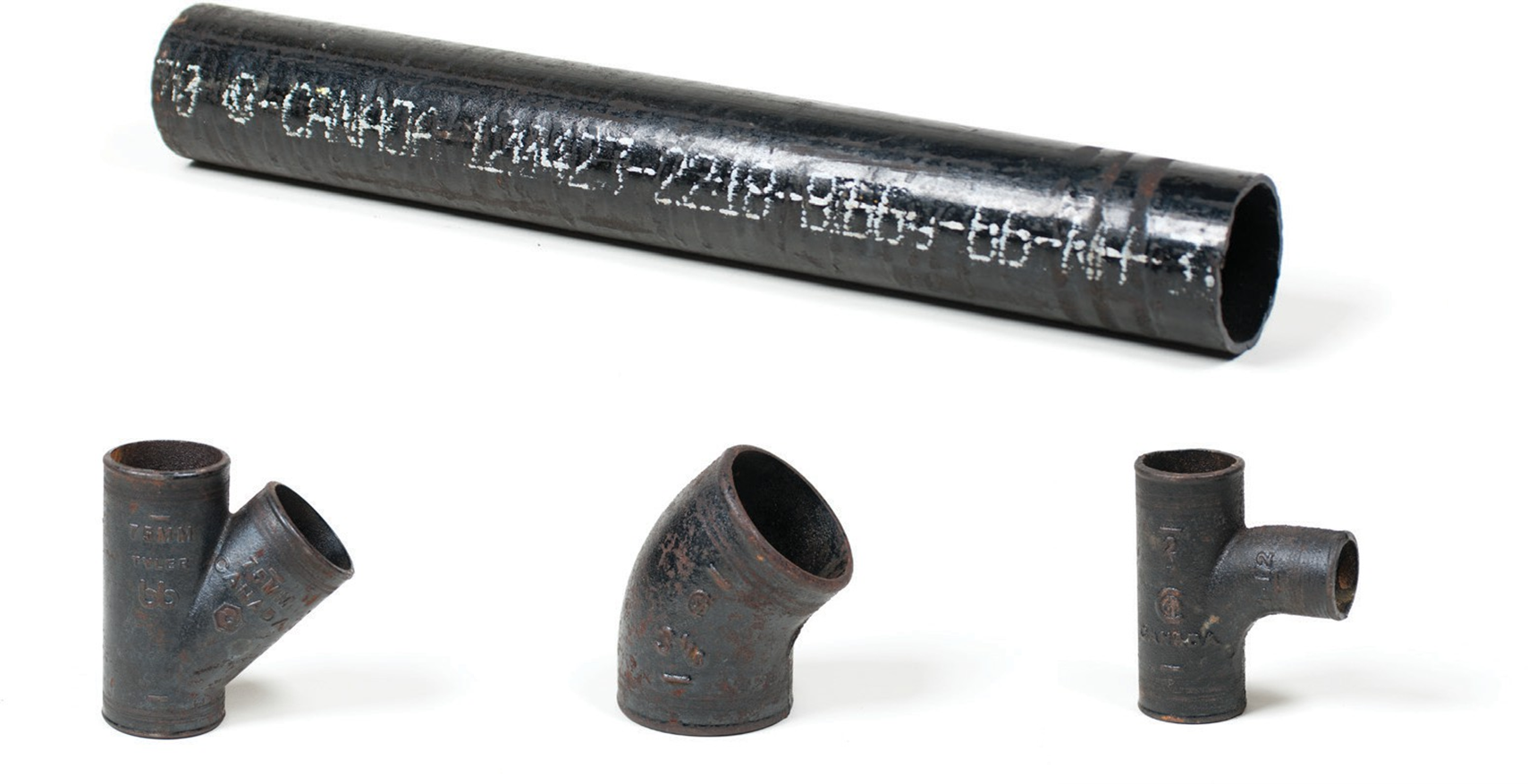
The basic raw materials used to produce cast iron soil pipe and fittings are scrap iron, scrap steel, alloys, coke, and limestone. These materials are melted in a cupola furnace to produce molten iron.
The casting of melted cast iron from the furnace into soil pipe and fittings is done by pouring the molten cast iron into casting moulds for fittings and using a centrifugal casting process for pipe. Metal moulds used in centrifugal pipe casting machines are spun on rollers and externally cooled by water.
Coatings are applied to the metal mould’s surface preventing sticking of the molten cast iron. As the cylindrical metal moulds spin, specific amounts and weight of molten cast iron are poured in. Centrifugal force distributes the molten cast iron to the inside surfaces of the spinning cylinder. The molten cast iron is allowed to cool and is removed from the metal cylinder as cast iron pipe. The cast iron pipe and fittings are inspected, tested, and dip coated to provide a smooth finish and protective coating. The finished pipe and fittings are ready for storage for shipment.
Cast iron soil pipe fittings may be produced by two different static casting processes: one process casts fittings in sand moulds and the other method employs permanent metal moulds.
First, moulds are made, then molten cast iron is poured into each mould. After the cast iron has cooled, the fittings can be removed from the moulds. The fittings are cleaned, inspected, tested and coated the same way as the pipe.
Copper Tube Manufacturing Process
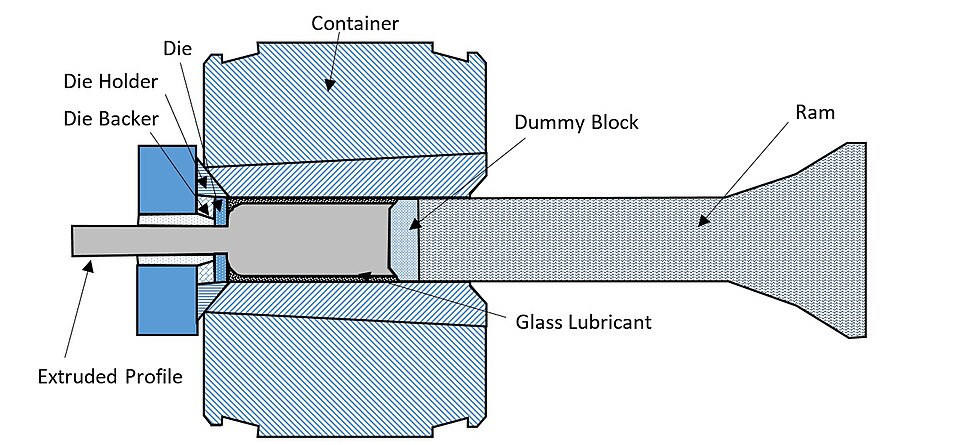
Copper and copper alloy tube is manufactured by the extrusion method. A headed copper billet is heated then forced through a die orifice and over a mandrel to form a hollow tube. The mandrel is held in position within the die orifice.
Another method uses rotary piercing. One end of a heated cylindrical billet is fed between rotating work rollers and is driven forward toward a piercing plug. In the mid-1960s, welded copper tube produced from strip without the use of a filler metal became commercialized.
Temper describes the strength and hardness of the tube. Drawn temper is often referred to as “hard,” while annealed temper is called “soft.”
Product Specifications (ASTM)
- Copper tube is a minimum of 99.9% pure copper.
- The copper used for tube supplied is deoxidized with phosphorus.
- Types K, L, M, DWV, and medical gas tube are designated by ASTM standard nominal inside diameter sizes. The actual outside diameter is always [latex]\frac{1}{8} \text{"}[/latex] larger than the standard size designation.
- Copper used in medical gas and air conditioning and refrigeration systems is ordered degreased and capped. The plastic capped ends stay on the pipe until just before installation.
- Each copper tube type represents a series of sizes with different wall thicknesses. Type K tube has thicker walls than Type L tube, and Type L walls are thicker than Type M, for any given diameter. All inside diameters depend on tube size and wall thickness.
- Copper tube for air-conditioning and refrigeration field service (ACR) is designated by actual outside diameter.
“Temper” describes the strength and hardness of the tube. In the piping trades, drawn temper tube is often referred to as “hard” tube, and annealed as “soft” tube.
Table 1 identifies the six standard types of copper tube and their most common applications. The table also shows the ASTM standard appropriate to the use of each type along with a listing of its commercially available lengths, sizes and tempers.
|
Tube Type |
Colour Code |
Standard |
Application (See note 1) |
Commercial Available Lengths (See note 2) |
||
|
Type K |
Green |
ASTM B 88 (See note 3) |
|
Straight Lengths |
||
|
0.25″ to 8″ |
20′ |
20′ |
|||
|
10″ |
18′ |
18′ |
||||
|
12″ |
12′ |
12′ |
||||
|
Coils |
||||||
|
0.25″ and 1″ |
– |
60′ |
||||
|
– |
100′ |
|||||
|
1.25″ and 1.5″ |
– |
60′ |
||||
|
2″ |
– |
40′ |
||||
|
– |
45′ |
|||||
|
Type L |
Blue |
ASTM B88 |
Domestic water service and distribution Fire protection Solar Fuel/fuel oil Natural gas Liquified petroleum (LP) gas HVAC Snow melting Compressed air Vacuum |
Straight Lengths |
||
|
0.25″ to 10″ |
20′ |
20′ |
||||
|
12″ |
18′ |
18′ |
||||
|
Coils |
||||||
|
0.25″ to 1″ |
– |
60′ |
||||
|
– |
100′ |
|||||
|
1.25″ to 1.5″ |
– |
60′ |
||||
|
2″ |
– |
40′ |
||||
|
– |
45′ |
|||||
|
Type M |
Red |
ASTM B88 |
Domestic water service and distribution Fire protection Solar Fuel/fuel oil HVAC Snow melting Vacuum |
Straight Lengths |
||
|
1.25″ to 12″ |
20′ |
N/A |
||||
|
DWV |
Yellow |
ASTM B 280 |
Drain, waste, vent HVAC Solar |
Straight Lengths |
||
|
0.25″ to 8″ |
20′ |
N/A |
||||
|
ACR |
Blue |
ASTM B 280 |
Air conditioning Refrigeration Natural gas Liquefied petroleum (LP) gas Compressed air |
Straight Lengths |
||
|
[latex]\frac{3}{8} \text{"}[/latex] to 1[latex]\frac{1}{8} \text{"}[/latex] |
20′ |
N/A |
||||
|
Coils |
||||||
|
[latex]\frac{1}{8} \text{"}[/latex] to 1 [latex]\frac{5}{8} \text{"}[/latex] |
20′ |
(See note 4) |
||||
|
OXY, MED OXY/MED OXY/ACR ACR/MED |
K) Green (L) Blue |
ASTM B 819 |
Medical gas Compressed medical air Vacuum |
Straight Lengths |
||
|
[latex]\frac{1}{4} \text{"}[/latex] to 8″ |
|
|
||||
|
||||||
Plastic Pipe Manufacturing
Acrylonitrile-Butadiene-Styrene (ABS)
Acrylonitrile-butadiene-styrene (ABS) cell core is made using an extruding head that allows air to be inserted in the middle of the pipe. It uses less resin and creates a less expensive pipe that doesn’t affect the structure of the pipe and its resistance to pressure.
Polyethylene Pipe
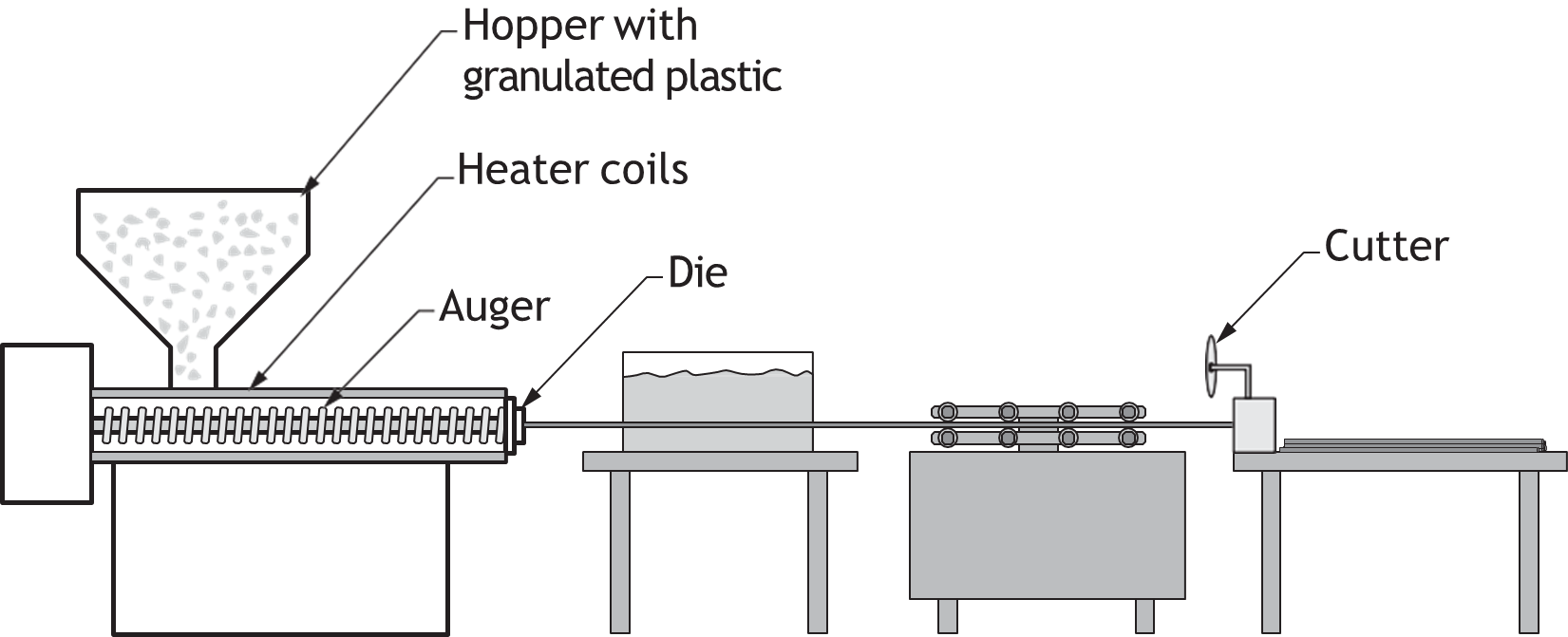
Polyethylene (PE) pipe is produced by heating raw plastic pellets and forming them through an extrusion process. Colour pigments are added depending on the application (e.g., yellow for gas, black for general use). The essential steps of polyethylene (PE) pipe and fitting production are to heat the raw pellet material into a particular shape and hold that shape during the cooling process. This is necessary to produce solid wall and profile wall pipe as well as compression and injection moulded fittings. All diameters of solid wall PE pipe are continuously extruded through an annular die.
The raw material is typically supplied to the pipe producer as non-pigmented pellets. PE pellets are stabilized for both heat and UV protection. Usually, colour pigment is added to the pipe at the producer’s facility. In North America, the most common colours are black and yellow. The choice of colour will depend upon the intended application and the requirements of the pipe purchaser. Carbon black is the most common pigment used for water, industrial, sewer and above-ground uses. Yellow is reserved exclusively for natural gas applications, although black with yellow stripes is also permitted for this application. Other colours are used for telecommunications and other specialty markets.
Cross-Linked Polyethylene
Cross-linked polyethylene (PEX) is a polymeric material formed by chemically joining of individual polyethylene (PE) molecules in a process called cross-linking.
There are three main methods used to accomplish the molecular cross-linking:
- PEX-A (peroxide method) is produced by the peroxide (Engel) method. This method performs “hot” cross-linking, while the polyethylene is above its melting point before extrusion. The process takes slightly longer than the B and C methods because the molecular plastic polymer has to be kept at high temperature and pressure for long periods during the extrusion process. This PEX is the only type of PEX that can be kinked and fully repaired using low heat.
- PEX-B (silane method) is produced by the silane method, also called the “moisture cure” method. In this method, cross-linking is performed after the extrusion process, producing cross-links between a cross-linking silane related agents. After installation, PEX-B has the same properties as PEX-A.
- PEX-C (electron beam method) is produced through electron beam processing after extrusion in a “cold” cross-linking process. This process has lower uniformity of cross-linking than the PEX-A especially at tube diameters over one inch (2.5 cm). When the process is not controlled properly, the outer layer of the tube may become brittle. However, it’s the cleanest, most environmentally friendly method because it does not involve other chemicals to create the cross-linking.
PEX Piping Qualities
- PEX tubing and PEX fittings come in sizes ranging from [latex]\frac{1}{4} \text{"}[/latex] – 2″ in diameter in North America, whereas in Europe, PEX pipe is available in sizes up to 6″.
- Manufactured to copper tubing size OD controlled (CTS-OD) dimensions.
- Sold in coils and straight lengths.
- The wall thickness is based upon SDR 9 values, which yield pressure ratings of 160 psi at 73°F and 100 psi at 180°F.
- Some manufacturers have their tubing rated to 200°F with an 80 psi maximum working pressure.
- Some PEX fittings should only be joined to specific PEX tubing, as recommended by the pipe manufacturer.
PVC Pipe Manufacturing
The technology of the Polyvinyl chloride (PVC) pipe manufacturing processes is extensive and involved. It can be traced from oil or gas wells through petrochemical plants to the PVC compounding operations and finally to the automated extrusion, moulding and fabrication operations before a finished PVC product is ready for testing, inspection, and delivery.
The raw plastic PVC compounds are prepared and heated. The heated elastic plastic is extruded into the pipe-forming die under high pressure (2000—5000 psi). In the pipe extrusion die, the hot plastic material is moulded into a cylindrical shape. As it leaves the extrusion die at the exit orifice, the material is extremely hot (about 400°F), flexible, and pliable. In this state, the hot plastic is formed with dimensional accuracy into a finished product and then cooled into a solid state. The extruded PVC pipe is drawn away from the extruder into cooling tanks where it’s cooled by chilled water. By the time the pipe emerges from the end of the cooling tanks, it has cooled to a temperature where it can be handled without distortion. After leaving the cooling station, the pipe travels through a printing station. Pertinent product and process information is printed on the PVC pipe. Beyond the printer, the pipe is automatically cut to the correct length. The ends are trimmed to specifications depending on its intended use.
 Self-Test D-1.2: Describe the Methods of Manufacture of Piping and Tubing
Complete Self-Test 2 and check your answers.
If you are using a printed copy, please find Self-Test D-1.2 and Answer Key in the Appendix at the end. If you prefer, you can scan the QR code with your digital device to go directly to the interactive Self-Test.

References
ASTM International. (n.d.). Book of ASTM standards by section. https://www.astm.org/standards-and-solutions/bos#standards-by-section
BC Industry Training Authority. (2019). Piping trades apprenticeship program: Use Tools and Equipment—Level 1 harmonized [Binder]. Crown Publications, Queen’s Printer for British Columbia. https://www.crownpub.bc.ca/Product/Details/7960000261_S
- Plumber: Competency D-1 Prepare Pipe
- Steamfitter: Competency D-4 Layout and Install Piping and Tubing
- Sprinkler Fitter: Competency D-1 Prepare Pipe and Tubing
CSA Group. (n.d.). Standards. https://www.csagroup.org/standards/
Government of British Columbia. (2025). BC building code 2024. https://www2.gov.bc.ca/gov/content/industry/construction-industry/building-codes-standards/bc-codes/2024-bc-codes
Government of British Columbia. (2025, June 10). BC plumbing code 2024. https://www2.gov.bc.ca/gov/content/industry/construction-industry/building-codes-standards/bc-codes/2024-bc-codes/plumbing
Lee, R. A. (2006). IPT’s pipe trades handbook and training manual. IPT Publishing and Training Ltd. https://iptbooks.com/pipe-trades/
Media Attributions
All figures are sourced from Industry Training Authority (2019) and/or Camosun College (2019) and are used under the Creative Commons Attribution 4.0 (CC BY 4.0) licence unless otherwise noted. Images copyrighted by the BC Industry Training Authority are licensed under a Creative Commons Attribution-NonCommercial-ShareAlike 4.0 (CC BY-NC-SA 4.0) licence.
- Figure 7 Schematic of metal extrusion process by Vivekverma239 from Wikimedia Commons is used under a CC0 1.0 public domain license.
A method of making pipe by heating and welding the edges of steel together using electricity. (Section D-1.2)
A strip of steel that is formed into pipe during manufacturing. (Section D-1.2)
A solid piece of metal that is heated and shaped into pipe or tubing. (Section D-1.2)
A tool placed inside a pipe during manufacturing to shape and size it. (Section D-1.2)
A process of joining metal by heating it until it melts and fuses together, often forming a continuous seam along the pipe. (Section D-1.2)
A type of steel pipe made by rolling a strip of steel into a spiral shape and welding the seam along its length. (Section D-1.2)
A pipe welding method where both the inside and outside seams are welded under a protective layer. (Section D-1.2)
A welding method where the weld is protected by a layer of material during the process. (Section D-1.2)
A material used during welding to protect the metal from air and impurities. (Section D-1.2; Section D-1.6)
A method of making large steel pipe by pressing a flat steel plate into a “U” shape and then into an “O” shape before welding it into a cylinder. (Section D-1.2)
A method of making pipe by rolling a flat steel plate into a round shape using three rollers, then welding the seam to form a cylinder. (Section D-1.2)
inner diameter
outer diameter
A type of furnace used to melt metal, especially iron, by heating it with coke and air to produce molten metal for casting. (Section D-1.2)
A method of making pipe by pouring molten metal into a spinning mould so the material spreads evenly along the inside surface. (Section D-1.2)
A process where heated material is pushed through a shaped opening to form pipe. (Section D-1.2)
A method of making pipe by rotating a heated solid metal piece and pushing it over a tool to form a hollow tube. (Section D-1.2)
The hardness and strength of metal, based on how it is heated and cooled. (Section D-1.2)
A hard and strong type of copper tubing made by pulling the metal through a die without heating it. (Section D-1.2)
A soft and flexible type of copper tubing made by heating the metal and then slowly cooling it. (Section D-1.2)
A strong, lightweight plastic used to make pipes and fittings, especially for drainage, waste, and vent systems. (Section D-1.2)
A type of plastic commonly used to make pipes. (Section D-1.2)
A flexible plastic pipe made stronger by a chemical bonding process. (Section D-1.2)
A chemical process that joins plastic molecules together to make the material stronger. (Section D-1.2)
A type of PEX tubing made using the peroxide (Engel) method, known for being flexible and able to be repaired with heat. (Section D-1.2)
A type of PEX tubing made using the silane (moisture cure) method, known for its strength and resistance to pressure. (Section D-1.2)
A type of PEX tubing made using an electron beam process, known for being more rigid and less evenly cross-linked than other types. (Section D-1.2)
A strong plastic material used to make pipes for water and drainage systems. (Section D-1.2)