D-4.1 Describe Factors Affecting Penetrations in Structures
As a pipe trades worker, it is your job to install, maintain, and repair piping systems and components. Much of the pipe you install will be within structures and will penetrate through foundations, walls, floors, ceilings, and roofs. When installing piping systems, you must maintain the integrity of the structure. You should be able to correctly make pipe penetrations through building structural components.
On the job, you should be aware of the function of the various building structural components. You cannot simply remove, cut, notch, drill, or otherwise alter a building’s structural components without considering the effect you are having on that structural component’s purpose.
Structural Integrity
Structural integrity is the ability of the structural component to perform its designed purpose.
When penetrating structural components with piping, you must consider, identify, and maintain the following:
- Structural support integrity of beams, columns, walls, floors, roofs, and ceilings
- Fire safety integrity of fire-rated assemblies, including firestops, firewalls, and separations
- Humidity, moisture, and water penetration integrity of the structure, roofs, walls and foundations, including protection against rain and groundwater penetration
- Energy efficiency, including heat loss and gain, insulation, and air barrier integrity
- Air quality, ventilation, air conditioning, and heat recovery system integrity
- Occupant health and safety integrity
- Appearance and environmental integrity
- Non-interference with adjoining properties
- Sound penetration integrity
- Other engineered structural concerns and requirements
You must have a clear understanding of the design purpose of the structural components within a structure. Every pipe system component installed must not compromise the structural integrity of the building. The following information identifies the related structural components of the building and the acceptable methods for penetrating piping components.
Wood-Frame Construction Components
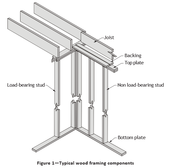
The following definitions are important in understanding the restrictions around cutting floor, roof, and ceiling framing members:
- Load-bearing structural member: A structural element designed to support the load above it, such as a second storey or roof. Cutting, drilling, or removing this support will weaken the structure.
- Non-load-bearing structural member: A structural element that is installed as a partition to divide space and does not support the weight above it. Cutting, drilling or removing this support will not weaken the structure.
Fire Separation
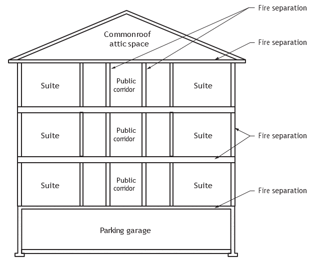
A fire separation is a construction assembly that resists the spread of fire. A fire separation is constructed of components that make up a fire-rated assembly or system. The fire rating of each component in the assembly contributes to the final fire rating for the fire-separation assembly.
Figure 2 shows a typical application of vertical and horizontal wood-frame fire separations and their locations.
Firewalls
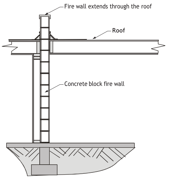
A firewall is defined by a building code as a type of fire separation made of non-combustible construction that subdivides a building, or separates adjoining buildings, to resist the spread of fire and remain structurally intact for the required period of time. Typically, a firewall is constructed of concrete or concrete block. A firewall has a higher overall fire rating than a fire separation.
An example of a firewall in a multi-storey wood-frame building is a concrete block wall that extends from the ground floor right up through the roof (Figure 3).
Party Walls
A party wall is a fire-separation wall jointly owned and used by two parties under an easement agreement or by right in law, and erected at or upon a line separating two parcels of land, each of which is capable of being a separate real estate property.
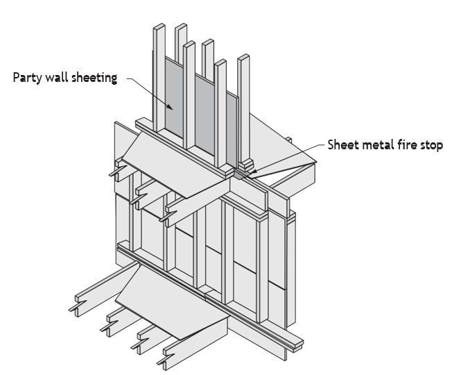
An example of a fire separation in a multi-storey wood-frame residential building would be the party wall that is required between the suites and the wall between the suite and the community hallway. Both of these walls must meet a fire rating that is specified in the building code.
The party wall shown in Figure 4 separates two suites and acts as a fire separation and a sound barrier. The wall consists of a double wall with an air space between. One wall is sheeted on the inside, and each floor has a sheet metal firestop.
Note: Plumbing pipes should not be placed inside a party wall. Check with the authority having jurisdiction.
It is critical that piping systems do not compromise the integrity of fire separations, walls, and firestops.
Glued, Laminated Beams
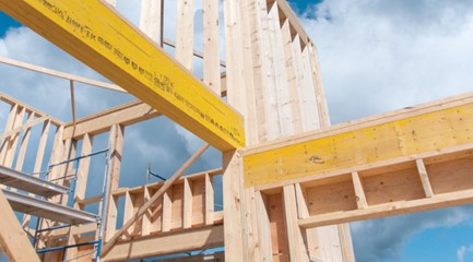
Glued-laminated beams are commonly referred to by a variety of names, such as glulam and paralam. A glued-laminated beam consists of multiple layers of thin strips of wood glued together to create a beam of standard dimensions.
In general, avoid drilling or notching glued-laminated beams. However, the Engineered Wood Association (APA) says that you can field-drill small-diameter holes for wiring and conduit. The location, size and number of these holes are restricted. You must consult with the manufacturer and confirm with the inspection regulatory authority. Avoid cutting, notching or drilling laminated beams unless the manufacturer, engineer and building officials specifically approve. Always consult the manufacturer’s specifications and regulatory authority before making any modifications.
Fire-Blocks
A fire-block is a firestop material installed during construction. A fire-block should not be confused with a firestop. Firestops are required when a higher degree of fire protection is required, particularly when there are penetrations through fire-rated separations. Firestops are covered in D-4.2 Describe Acceptable Methods of Structure Penetration. Fire-blocking involves field-installing building materials to prevent undetected flames and gases from moving through concealed spaces to other areas.

Do not remove or damage fire-blocks, as this will compromise fire safety.
During a fire, flame and heated products of combustion can spread via paths of least resistance. Certain structures, particularly wood-frame structures, have concealed voids or cavities within walls, ceilings, attics, and crawl spaces. These concealed spaces not only affect the spread of fire, but also make suppression more difficult. Frequently, and inevitably, pipes, vents, ducts, and similar items will penetrate fire-blocks. You must be able to recognize a fire-block when you see one so that you do not remove it or otherwise jeopardize its ability to restrict the spread of flames and gases.
Fire-blocks are required in the following locations:
- Between floors
- Between a top-storey and a roof or attic space
- In furred spaces or the cavities between studs in wall assemblies
- At connections between horizontal and vertical spaces created in floor joists or trusses, soffits, drop or cove ceilings, combustible exterior wall finishes and architectural elements
- Openings for pipes, vents, ducts, chimneys and fireplaces
Fire-blocks can be constructed of various materials, including:
- 2 inch nominal lumber
- Structural wood panels
- Gypsum board (drywall)
- Cement fibreboard for larger fire-blocks
- For smaller fire-blocks, batts or blankets of mineral wool or glass fibre, loose fill insulation and caulks, sealants, and putties
Check with the local authority having jurisdiction for appropriate fire-block material.
Figure 6 shows a fire-block in an attic space.
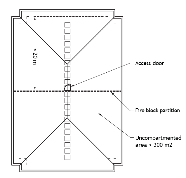
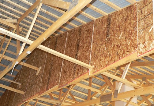
Figure 7 shows an example of an attic firestop under construction. Any items penetrating this firestop will need to be fire blocked to prevent rapid fire spread.
Wood-Frame Construction Penetrations
One important consideration when installing piping in wood-frame buildings is the placement of piping to avoid interfering with the integrity of the building’s structural supports. Normally, drilling and notching structural support members is not permitted. There may be exceptions to this rule; however, consultation with and approval by engineers and building officials will be required.
The following information is generic in nature and is not specific to a particular code wording or manufacturer’s specifications. The information is based on references to the BC Building Code and manufacturer’s information. On the job you will need to reference the building code and specific manufacturer’s specifications for drilling and cutting of building framing.
Cutting Holes in I-Joists
Today, wood-based lightweight I-beams (also called I-joists) (Figure 8) are widely used in the construction industry. An important feature of these beams is that holes may be cut in the web, but not in the flange.
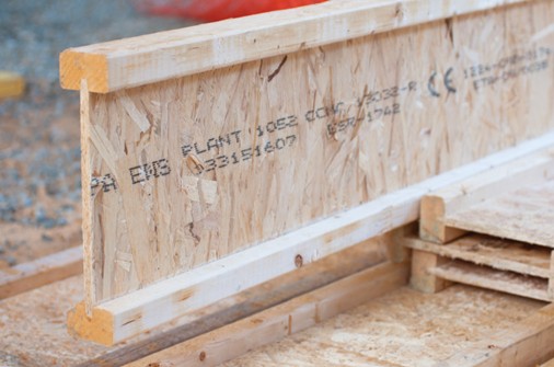
Hole-cutting specifications for wood I-joists:
- Round holes do not have to be centred on the joist centre but must not be closer than 1.25 cm ([latex]\frac{1}{2}[/latex] in.) from the joist flange.
- Do not cut or damage the joist flange.
- A maximum of three holes is permitted per joist.
- Cut all holes carefully.
- When more than one circular hole is cut, the distance of uncut web between the holes (Figure 9) must be twice the diameter of the largest diameter hole. For square holes, the minimum distance of uncut web between the holes must be two to four times the length of the largest adjacent hole.
- A maximum size of 3.75 cm (1 [latex]\frac{1}{2}[/latex] in.) holes may be cut anywhere in the web, provided the centre-to-centre measurement is 30 cm (1 foot) on centre.
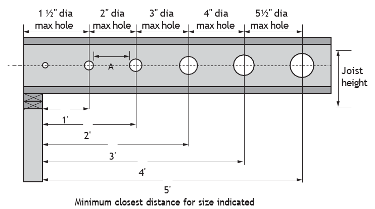
Figure 9 shows the typical maximum dimensions for round hole diameters and the minimum distance from the bearing support for joist depths of 237.5, 298 and 350 mm (9.5 in., 11[latex]\frac{7}{8} \text{"}[/latex] in. and 14 in.). Consult the manufacturer’s specifications before cutting any holes.
- Square cut holes must be centered on the web.
- Some manufacturers require square or rectangular holes to be located in the middle third of the span.
- Some manufacturers will not allow any holes in a joist within 120 cm (48 in.) of the supporting member (Figure 10).
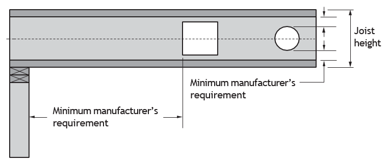
Observe the following rules when cutting a laminated I-joist:
- Do not cut, drill, notch or chisel the flange.
- Do not over-size the holes in the web.
- Do not break out holes with a hammer.
- Do not cut holes too close to the bearing supports.
Do not assume that it is OK to cut or drill a hole in a beam for a small pipe. Always consult with the manufacturer’s specifications, regulatory codes, inspection authority and design engineer before attempting to drill or cut a structural support. The job site supervisor (general contractor) would be a good source of information.
Specifications for Holes in Glued, Laminated Beams
Examples of access holes include those used for the passage of wires, electrical conduit, small-diameter sprinkler pipes, fibre-optic cables, and other small, lightweight materials. These field-drilled horizontal holes should meet the following guidelines.
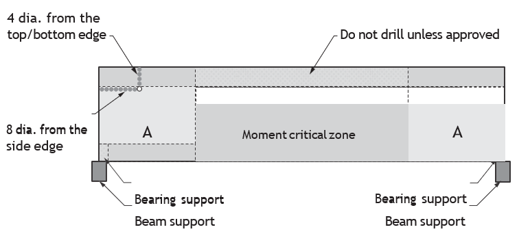
- The hole diameter should not exceed 38 mm (1.5 in.) or [latex]\frac{1}{10}[/latex] the beam depth, whichever is smaller.
- The minimum distance from the edge of the hole to the bottom or top edge of the beam is four hole diameters.
- The minimum distance from the edge of the hole to the end of the beam is eight hole diameters.
- Holes 25 mm (1 in.) diameter or smaller should not be drilled in the area above and below the center rectangle (Figure 11) unless approved by the design engineer and regulative authority. This area is called the moment critical zone. The dimension of the zone will be provided by the manufacturer.
- The horizontal hole should not be drilled in areas other than as defined in Figure 11 unless approved by an engineer or architect qualified in engineered timber design.
- Field-drilled horizontal holes should be used for access only and should not be used as attachment points for brackets or other load-bearing hardware unless specifically designed by the engineer or designer.
Notching and Drilling of Joists
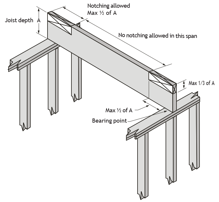
The BC Building Code advises that holes in roof, floor, or ceiling framing members shall not be larger than one-quarter the depth of the member and must be located at least 50 mm (2 in.) from the edge, unless the depth of the member is increased by the size of the hole (Figure 12).
Note: Round holes are preferred over square holes or notches.
Nominal vs. Actual Joist Dimensions
The actual dimension of a 2″ x 10″ joist is 1 [latex]\frac{1}{2} \text{"}[/latex] × 9 [latex]\frac{1}{2} \text{"}[/latex].
The actual size of a 2″ x 12″ joist is 1 [latex]\frac{1}{2} \text{"}[/latex] × 11 [latex]\frac{1}{2} \text{"}[/latex].
Maximum hole sizes are calculated based on actual dimensions rather than nominal dimensions, as follows:
- The maximum diameter hole in a 2″ × 10″ joist is [latex]\frac{23}{8} \text{"}[/latex].
- The maximum diameter hole in a 2″ × 12″ joist is [latex]\frac{27}{8} \text{"}[/latex].
Note: To obtain the metric dimensions use the conversion factor 1 in. = 25.4 mm. Actual metric dimensions of some common nominal sizes are:
- 2″ × 10″ nominal joist = actual size 38 mm × 241 mm
- 2″ × 1″ nominal joist = actual size 38 mm × 292 mm
A nominal 3 in. diameter pipe has an outside diameter of approximately 3[latex]\frac{1}{2} \text{"}[/latex] inches. The pipe therefore cannot be installed in a nominal 2″ × 10″ joist or 2″ × 12″ joist. A 3 in. pipe would require at least a 3[latex]\frac{5}{8} \text{"}[/latex] in. hole to allow for clearance. This would mean a minimum 16 in. joist is needed.
Note: Never notch the bottom of a joist or cut sections out of a joist.
The BC Building Code advises to avoid notching if possible, but notching floor, roof and ceiling framing members is permissible under the following restrictions (Figure 12):
- The notch must be located on the top of the member within half the joist depth from the edge of the bearing.
- The notch must be not deeper than one-third the joist depth, unless the depth of the member is increased by the size of the notch.
Notching or Drilling Studs or Plates
Notching and drilling studs and plates is acceptable as long as the following BC Building Code requirements are followed.
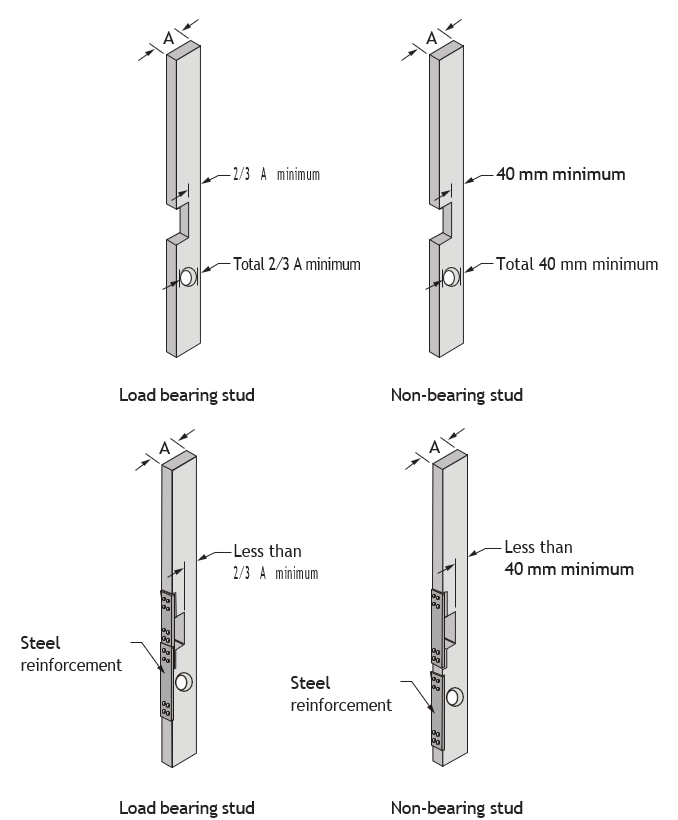
Wall studs must not be notched, drilled, or otherwise damaged so that the undamaged portion of the stud is less than two-thirds the depth of the stud if the stud is load-bearing, or less than 40 mm (1.6 in.) if the stud is non-load-bearing, unless the weakened studs are suitably reinforced.
Top Plate Drilling and Notching (BC Building Code clause interpretation)
The top plates in a wall must not be notched, drilled or otherwise weakened by reducing the undamaged width to less than 50 mm (2 in.), unless the weakened plates are suitably reinforced (Figure 14).
Note: A 3 in. pipe cannot be installed through a 2″ × 6″ plate without additional reinforcement. Likewise, a 1 [latex]\frac{1}{2} \text{"}[/latex] in. pipe cannot be installed through a typical 2″ × 4″ plate without reinforcing.

Top Plate Reinforcement
When a hole that is larger than permitted is cut in a plate, reinforcing must be installed, as shown in Figure 15.
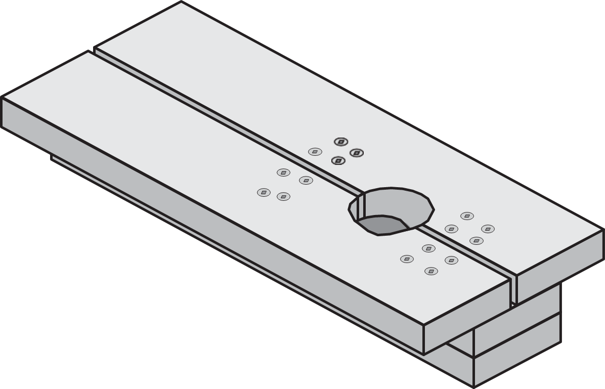
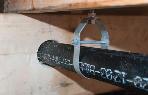
The top and bottom plates or tracks of the walls are sometimes riddled with openings for pipe and cable penetrations. The extent of such holes can affect the structural integrity of the wall. The practice of installing an excessive number of openings too close together should be avoided.
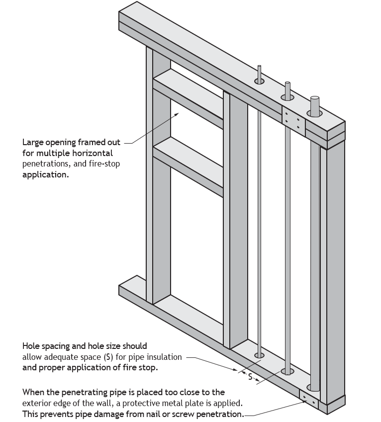
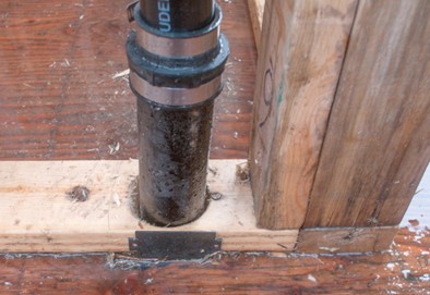
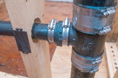
When the penetrating pipe is placed too close to the exterior edge of the wall, a protective metal plate is applied. This prevents pipe damage from nail or screw penetration.
Where the plate and stud wall do not make up a fire separation, they are not affected by firestop requirements. In this situation, the recommended practice is to space the holes so that the minimum distance between them is the same as or larger than the largest adjacent pipe’s diameter.
When a number of items are required to penetrate a fire separation, good practice dictates that they be spaced in such a manner that each penetrating item is surrounded by sufficient firestop material and separated by sufficient base construction material to ensure the stability and integrity of the firestop.
Sound Transmission Barrier Penetrations
Another important design feature in a structure is the elimination of sound transmission within the building. It is clear that an increase in sound transmission will occur when an opening is provided for the installation of piping. When sound transmission reduction is a component part of the structure then steps need to be taken to maintain the sound transmission integrity.
You need to identify the structural components that may require sound transmission reduction. Identifying locations where a sound barrier component is needed is not easy. Some things you need to look for include:
- Walls between occupancies (e.g., a library and a restaurant)
- Walls between a bathroom and an entertainment room
When pipe penetrates through or contacts a structural member that is acting as sound barrier, the structure’s sound integrity can easily be destroyed. Pipe installed within a wall may not penetrate the wall; however, a pipe contacting a structure component can transmit and amplify sound throughout the structure. The use of sealed pipe sleeves, insulators, or vibration isolators can eliminate or reduce sound transmission. Avoid direct contact with the structural components.
Some visual indicators to help identify sound transmission barriers include:
- Walls with offset studs
- High-density insulation in interior walls
- Party walls between occupancies; these are usually double-stud wall fire separations containing a 25 mm (1 in.) air space between the stud walls
- Double layer of wall boarding
- Public corridor walls between the corridor and residential suites; these are usually single walls with smaller offset studs on a larger plate
- Firewalls and fire separations often have sound barrier qualities
- Floor assemblies between residential suites
To reduce sound transmission for vertically installed pipes, install the pipes as follows:
- In multi-storey buildings, install the piping in furred outer walls in front of double-stud walls, fire separations or party walls, or other interior walls; or
- Install the pipe in framed-out service spaces.
Note that wastewater flowing through an ABS pipe is considerably noisier than that flowing through a cast iron waste pipe.
For horizontally installed pipes in a multi-storey structure, install the pipe servicing the occupant unit located above within the rated floor assembly. Where possible, provide a false ceiling for services in the occupant unit below.
Typically, installing piping within or through walls, ceiling or floors will increase the possibility of sound penetration. You are responsible for maintaining the sound transmission prevention design integrity of a wall, ceiling or floor you are penetrating.
Protecting Pipe from Nail and Screw Damage
Figures 18 and 19 illustrate the proper application of pipe protection plates on studs where pipe is penetrating. When installing reinforcement on a stud surface, you must be aware of the thickness of the reinforcement plate. The thicker the plate, the more the wall finish will bulge, resulting in a product with a poor finish.
Residential Roof Penetrations
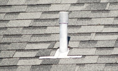
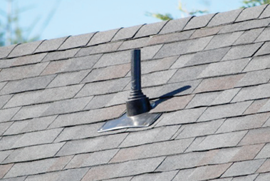
For new residential shingled roof applications, you would need to have the penetrating pipe installed before the roofing contractor arrives. You would supply the flashing and flashing cap. Place the flashing over the pipe for the roofer. If a flashing cap is required have that available for the roofer. The sealing of a pipe penetration is best left to the roofing contractor.
For existing shingled roofs, you may be required to waterproof the vent penetration. This may involve the use of counter flashing and waterproof sealing compounds. The plumbing code regulates the dimensions and material used for flashings as well as the size and distance above the roof that a vent pipe and flashing extend. In cold climates and conditions, the size of the penetrating vent pipe vent is increased. The increase in size helps prevent blockage caused by freezing over of the opening.
Figures 20 and 21 show vent pipe penetrations and flashings on sloped shingle roofs.
Wood Roof and Floor Trusses
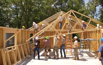
The BC Building Code advises that roof truss members (Figure 22) not be notched, drilled, or otherwise weakened unless such notching or drilling is allowed for in the design of the truss.
A roof or floor truss structural support should never be cut, drilled, notched or otherwise have its structural integrity jeopardized. It is a good idea for the piping installer to plan ahead for the routes that will be taken by the piping system. Conflicts with truss placement need to be solved before installing either trusses or piping.
Metal Roof Trusses
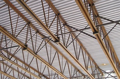
Do not cut, drill, notch, or remove a truss or component from a metal roof or floor truss.
Metal Decking
At times, you will work on jobs that use metal trusses and metal decking. Often the metal deck is covered with concrete. The floor is usually a fire separation. Firestopping and the installation of pipe sleeves or canning are often required.
Plumbing and mechanical system piping exiting through a roof require flashings to maintain structural integrity against moisture and rain penetration. Poor flashing installation or system design will increase the number of pipe penetrations and thus increase the possibility of jeopardizing the integrity of the roof structure. The trick here is to install the pipe through the roof and provide the flashing for the roofing contractor to install.
Penetrating Steel Columns and I-Beams
Steel columns and I-beams should not normally be cut or otherwise altered on the job.
Any holes required for pipe penetration should be done at the time of manufacturing. When holes are required in a beam or column, it is best to have them punched in the shop when the steel is fabricated.
Field holes may be cut in steel beams or columns; however, the approval of a structural engineer or competent architect would be required. Any holes would be cut in the middle third of the I-beam web. No holes are to be cut at all in the outer thirds of the beam. The hole may need to be reinforced. The specific holes should be approved by a design professional wherever they are to be cut, and they should be cut by a licensed welder.
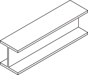
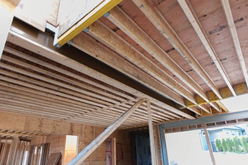
Figure 25 shows an I-beam supporting a wood deck. Do not cut or notch either of these structural support components.
Penetrating Steel Wall Studs
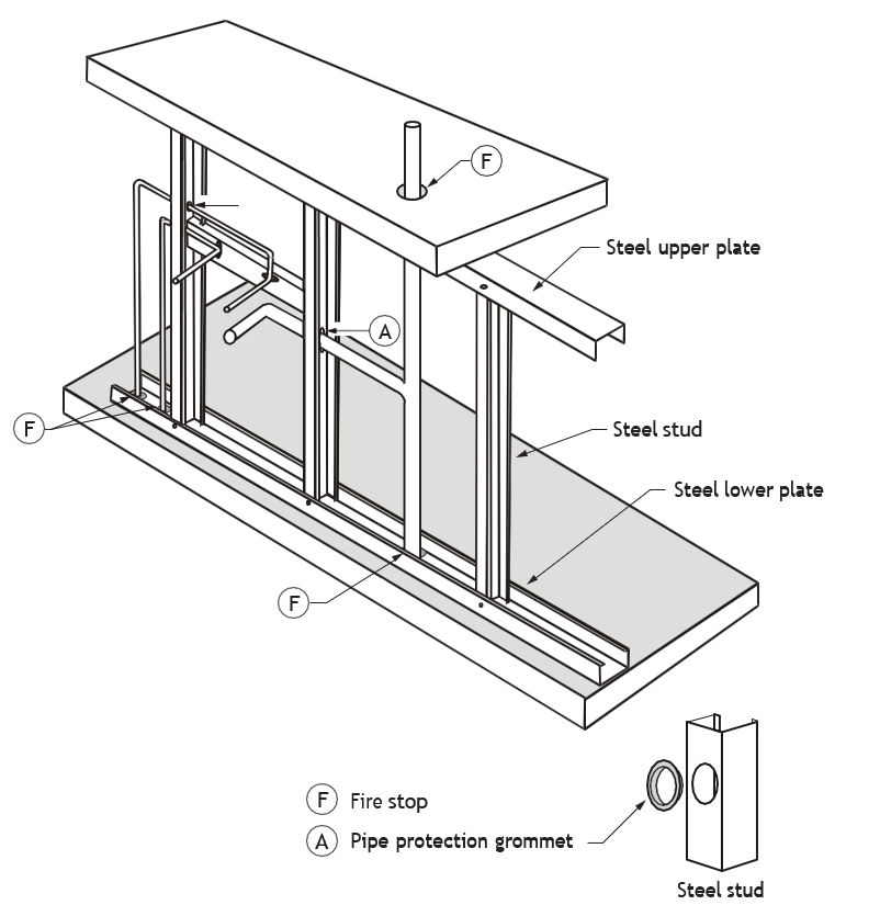
Steel studs typically are supplied with a limited number of precut holes. Where precut holes are not useful, new holes can be cut with sheet metal snips or a hole-punch.
Piping penetrating steel stud walls that serve as fire separations will require firestopping. Pipe located within the wall may require isolation from the steel components. Sharp steel edges can physically damage the pipe, especially plastic piping such cross-link polyethylene (PEX). Copper piping needs to be isolated from contact with the steel studs to avoid damage that contact between dissimilar metals can cause. This can be accomplished by grommets or by wrapping with electrical tape. See Figures 26 and 27.
Concrete slab is a fire separation between upper and lower floors. Firestopping is required at all pipe penetrations.
Penetrating Concrete Walls and Concrete-block Walls
Piping penetrations of concrete or masonry walls may require insulation, waterproofing, firestopping or protective pipe wrap placed around the pipe penetration. These measures ensure the integrity of the wall being penetrated.
You must be aware of the location of the web portion and the hollow portion of a concrete masonry block wall. Any pipe passing through the wall will ideally penetrate the hollow portion of the concrete block and not the web.
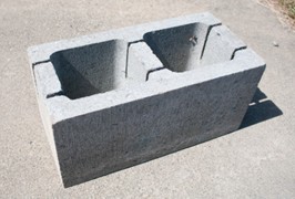
Figures 28 shows a concrete block with pre-cut knock-outs which may be used to install a bond beam.
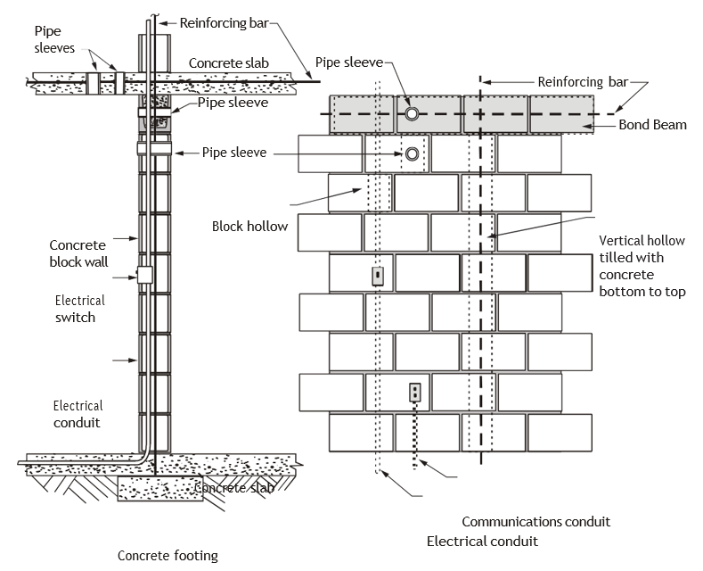
When penetrating a concrete block wall after it has been constructed, you need to locate the hidden components before you drill. The concrete block wall cross-section in Figure 29 shows pipe sleeves, bond beam and hidden components. The bond beam ties together and strengthens the concrete block wall. It is located at the last or top course of blocks.
Concrete Construction Formwork
When you are working on a job site where there is concrete construction, you may be penetrating concrete walls, floors and roof structures with piping. Openings in a concrete structure for the purpose of installing pipe are usually cast into the concrete by the use of pipe sleeves. This is done at the time of the concrete pour to avoid the expense of having to drill through the concrete after the concrete is cured.
Where holes need to be drilled in existing concrete, you need concrete drilling and breaking equipment and drill bits capable of cutting through rebar. The mechanical contractor may have these tools. If not, they can be rented. Companies that specialize in concrete drilling/coring can also be contracted to perform this task.
Before drilling or breaking into an existing concrete wall, you need to do some investigation to locate hidden reinforcing bars, electrical conduit and communication cables buried in the concrete. To avoid contacting these hidden components, locate and review existing construction plans. The building owner or the local government building inspection authority may have original drawings. Look for electrical equipment mounted on a concrete wall or ceiling. The absence of surface-mounted conduit may indicate that conduit is buried in the concrete. Pipe-locating companies may have equipment to detect hidden components.
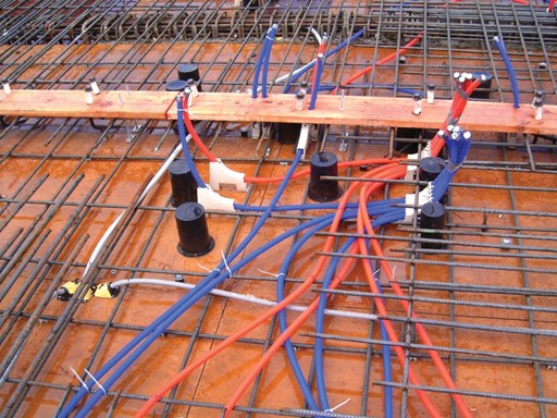
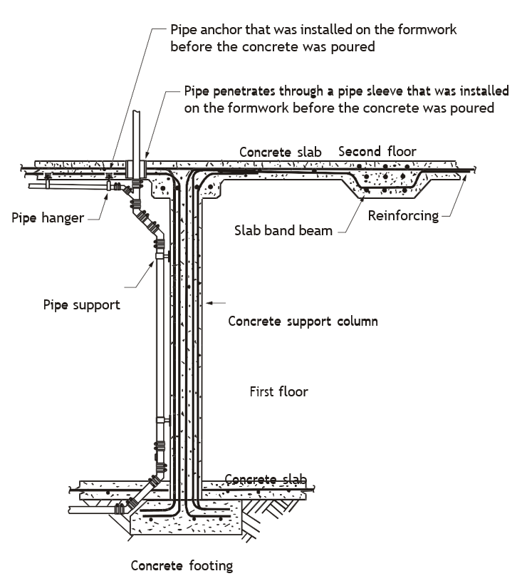
Figure 31 shows a cross section of a concrete construction. Notice the hidden structural components and the use of pipe sleeves to penetrate the slab.
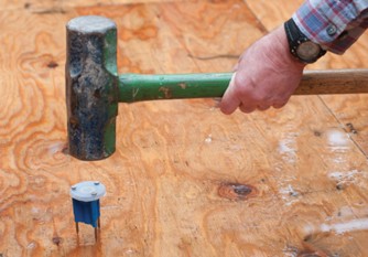
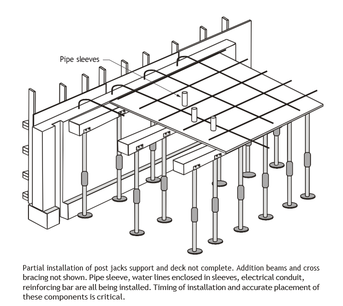
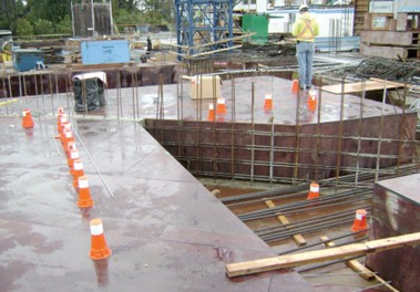
Figures 33 and 34 give an idea of the work environment in buildings with concrete structural components. Figure 33 shows the formwork being installed in preparation for the first-floor concrete slab. The teleposts (telescopic) support the formwork and the weight when the slab is poured. After the concrete has cured the post will be systematically removed in stages. The photo in Figure 34 was taken from above the posts. You would install pipe sleeves on the deck before the concrete is poured.
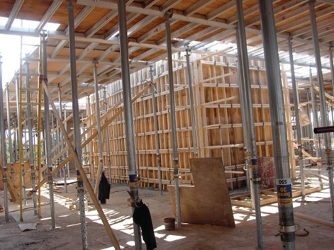
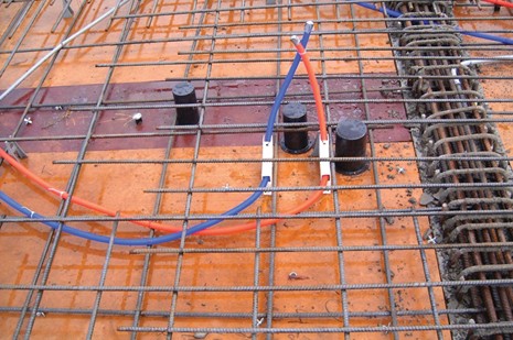
Figure 35 shows formwork for a foundation and the installation of pipe sleeves and block-outs. You would have located these sleeves and block-outs during this stage of construction.
As an alternate method of reinforcing concrete slabs with rebar, post-tension slabs can be installed. Cracking due to shrinkage is reduced and cracks that occur will be held together under the tension of the slab. Cables are installed in a slab before the concrete is poured. One end is anchored while the other end protrudes out the other side of the slab. These are referred to as tendons.
When the concrete has come to an appropriate strength, the cable will be stretched, cut off and grouted in place. Safety becomes an issue when coring or drill post-tension slabs. Cut tendons can cause structural damage and injury or death to workers. Locating tendons before coring is a one of the first steps when penetrating a post-tension slab. Small openings can be made using a coring machine. Large penetrations (ex. duct shafts) may require concrete sawing. Consult with a professional engineer before penetrating a post-tension slab.
Pipe Sleeves
A pipe sleeve is a hollow, cylindrical insert placed in a wall, floor, structural component or concrete formwork to allow a pipe to penetrate the structure.
Pipe sleeves are short pipes or tubes that act as a conduit for pipe that passes through walls, ceilings, floors, foundations, footings, and so on. Sleeves allow the pipe to move through the partition free of building weight, abrasion, or corrosion. In concrete construction a sleeve placed in formwork before a wall or floor is poured is sometimes referred to as a can. The process of installing these sleeves is often called canning.
The sleeve should be positioned to reflect the orientation of the pipe that will pass through it. A vertically installed pipe will require the pipe sleeve to be positioned vertically (plumb) above the formwork deck.
The term pipe sleeve also refers to protective pipe or tubing that surrounds a pipe carrying the fluid to be used. The sleeve protects the internal pipe from damage. Pipe sleeves may be used in corrosive ground conditions, concrete slabs, and under traffic ways. The pipe sleeve will allow the pipe to move freely and maintain a seal at the same time.
Fabrication of Pipe Sleeves (Pipe Chases or Block-Outs)
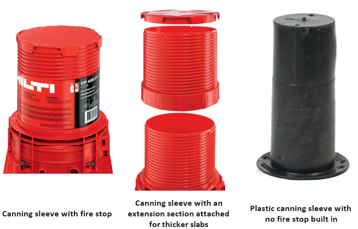
Pipe sleeves can be fabricated on the job site from materials such as steel, cast iron or plastic pipe, or from sheet metal. Pipe sleeves can also be purchased from a manufacturer as an assembly with firestop components. Pipe sleeves should be strong enough to resist the crushing weight of the surrounding building structure. The pipe should not normally bear weight or place any strain on the structure, unless the sleeve or pipe is designed to do so.
Placement of Pipe Sleeves
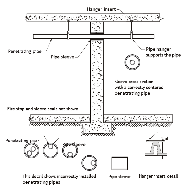
Multiple pipes penetrating a sleeve can create issues with application of pipe insulation, maintenance of proper clearances between pipe and the application of firestopping—avoid this practice!
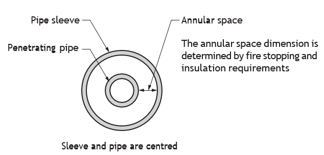
Pipe sleeves are ideally positioned so the pipe and the sleeve are centred with each other. The clearance around the pipe and the sleeve is referred to as the annular space. The annular clearance is often specified in the manufacturer’s firestop installation requirements.
Timing of Sleeve Installation in Interior Walls
Often, interior framed walls are installed after the piping has been installed. Where needed, pipe sleeves would be slipped over the pipe as the pipe is being installed. When the wall is installed, the pipe sleeves are already on the pipe. The sleeve must be positioned to the centreline of the penetrating pipe. Pipe insulation or some other method could be used to centre the pipe sleeve at the time of the pipe installation. If you leave the centring of the pipe sleeve up to another trade, chances are it will not happen. You will be left to centre the sleeve later. If the installation of the wall has locked the sleeve into an off-centre position, you may have some difficulty trying to centre the sleeve.
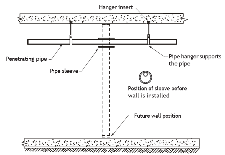
Sloped piping will require the sleeve to be sloped, or the sleeve must be sized large enough to allow the penetrating pipe to maintain slope through the sleeve.
Installing Sleeves in Deck Formwork (Canning)
Multi-storey, multi-unit office, and housing structures are often constructed with concrete floors and slabs for structural stability and load-bearing capacity. In these structures, a sleeve is a usually a length of pipe or tube that can be installed on or in concrete formwork before the concrete is poured. The sleeve provides an opening for pipe, conduit or communication cables after the concrete is cured.
Figure 39 shows examples of manufactured pipe sleeves that are installed during formwork for concrete structures. These sleeves are installed before the concrete is poured.
Sizing of Pipe Sleeves
The diameter of a pipe sleeve depends on the following:
- External diameter of the penetrating pipe
- Allowances for expansion and contraction of the pipe
- Allowances for the application of pipe insulation
- Annular space required for firestopping components
- Water and or vapour penetration prevention
- Air movement, drafts
The length of the sleeve will depend on the thickness of the finished wall or floor. In some instances, the sleeve may extend beyond the thickness of the floor to prevent flooding on the surrounding floor. The sleeve may extend to accept a sealing boot (Figure 40).
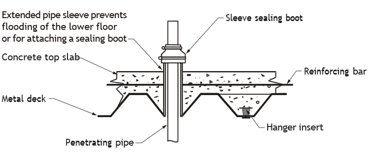
Threaded inserts are installed on the formwork deck at the same time as the pipe sleeves. They remain solidly embedded in the concrete after it has cured. The inserts support pipes suspended from the underside of the concrete slab.
Timing of Installation of Pipe Sleeves
The timing of sleeve installation is important. Pipe sleeves are installed when the foundation formwork is being constructed, before concrete slabs or walls are poured. They are also installed during construction of walls, such as concrete block walls.
When the formwork for a concrete slab is completed, several trades will begin work on the deck. The best opportunity to install pipe sleeves is before the reinforcing bar is installed, when the deck is clear of obstructions.
Construction-site scheduling usually has deadlines for specific stages such as the pouring of the concrete. The trades must communicate and cooperate with each other while on the deck to ensure there is no conflict between the placement of the various components. This is an important time for the whole job. It is not a matter of first-come first-served.
Positioning of Pipe Sleeves on Formwork
The correct positioning of pipe sleeves, block-outs and pipe support anchors is critical. Repositioning pipe sleeves after the concrete slab has set is costly and time consuming. Concrete walls and floors poured in place for multi-storey structures must be precisely positioned. Straight lines of pipe passing through a series of walls or floors will need pipe sleeves to line up perfectly from floor to floor or wall to wall. Bringing a pipe back into alignment can mean significant time and materials costs, so the alignment must be correct from the beginning.
Usually placement of a pipe sleeve (canning) would depend on the position of walls, structural beams and other building components. The sleeves are normally installed so that the penetrating pipe ends up in a wall. No walls are marked on the formwork deck. To be able to install the sleeve in the correct position, you will need to read the structure’s blueprint and specifications first. The blueprint alone will not be enough to locate the position of a sleeve. You will need to talk to the job general supervisor or charge-hand. A reference mark or grid line should be established and marked on the deck. This reference mark can be used by the different trades to establish a baseline from which measurements can be established.
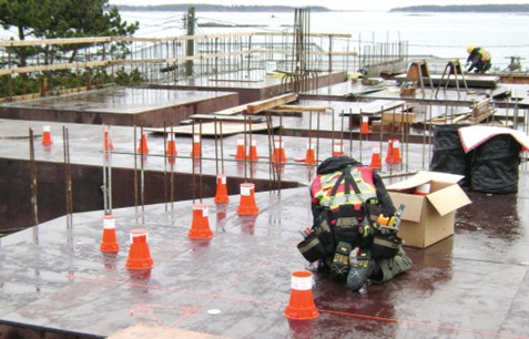
Once you have established the precise location of the sleeve, it can be attached to the deck. This measurement should be double-checked by the construction site supervisor. Laser-type levels are valuable assets for positioning sleeves and pipelines. String lines or chalk lines are used to establish a wall or other reference point on the deck; however, a caulk line does not last long in wet weather. The string line can be attached to the deck at one reference point, then stretched tight to another reference point on the deck.
Figure 42 shows a deck with string lines being used as a reference line to establish the position of the firestop pipe sleeves.
Fastening Pipe Sleeves and Protection During the Concrete Pour
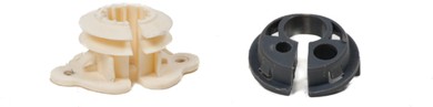
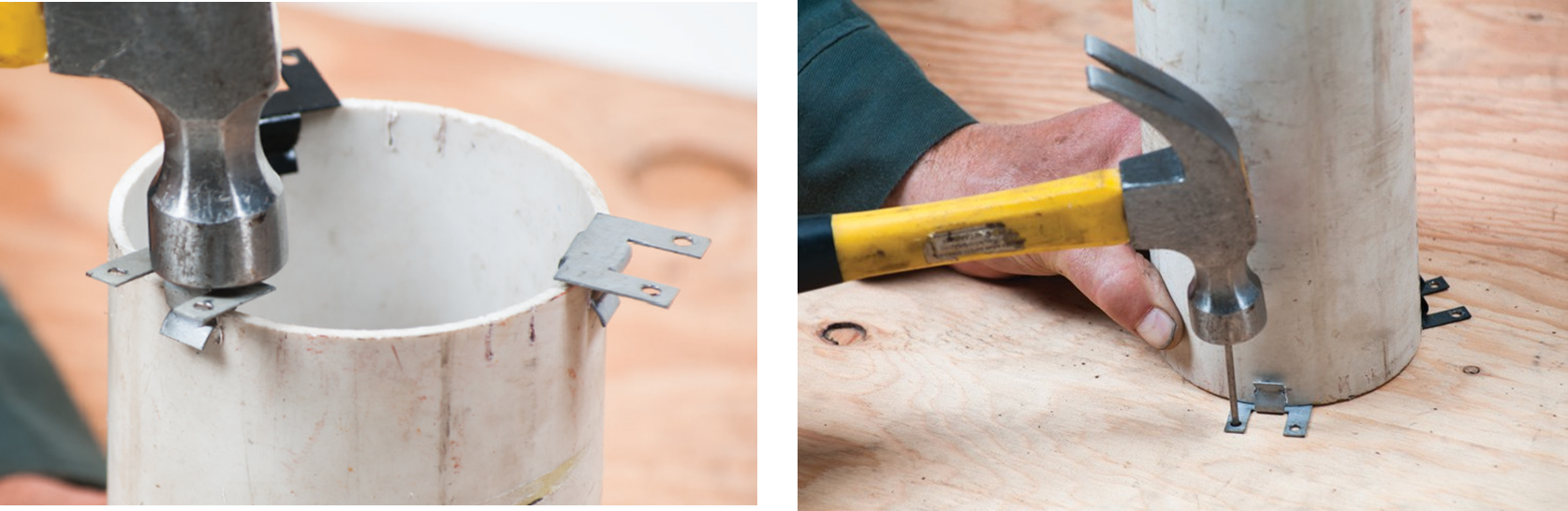
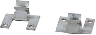
Field-cut pipe sleeves are anchored to the formwork deck using caddy clips, which clip onto the sleeves (Figure 43). The pipe clips are positioned and securely nailed or screwed to the formwork. The clips can accommodate various sizes of pipe and wall thickness up to schedule 80.
Figures 45 and 46 illustrate working conditions and how the piping and pipe sleeves are protected and secured.
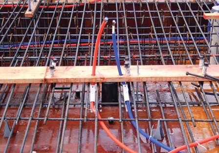
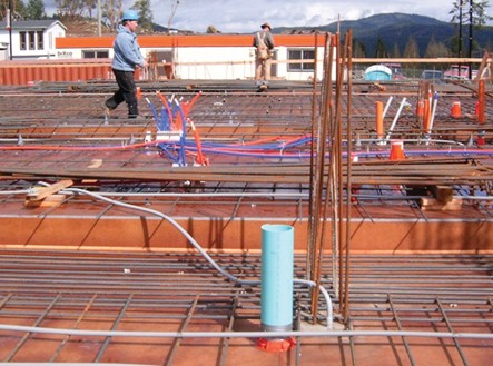
Several turns of tightly applied duct tape can be used to attach a sleeve extension to an existing sleeve. The sleeve can be kept in a vertical position by attaching it to the reinforcing bar using tie wire.
During concrete pouring, activity on the slab deck can dislodge or damage pipe sleeves and hanger inserts. You must be present during the concrete pour to observe and be ready to make quick repairs or reposition and place any sleeves or hanger inserts that are disturbed. If this is not done promptly, the sleeve may not be suitable for use after the concrete has set.
Installing Pipe Penetrations After Concrete Has Set
Omitting a sleeve or incorrectly positioning it during the formwork leads to extra cost and wasted time because the concrete has to be drilled (cored) after the concrete has cured and the formwork has been stripped. Job profitability is jeopardized.
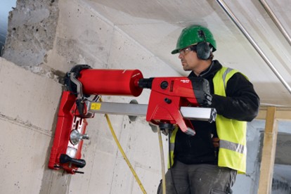
Normally you cannot simply break through a concrete slab or wall with jackhammer-type tools. Instead, the slab or wall will need to be cored with a rotary diamond-tipped core drill bit (Figure 47).
This type of drilling is usually done by specialized drilling companies using specialized concrete coring equipment. Electronic sensing equipment may be required to locate any hidden components before drilling.
Sealing Around Sleeves
The openings created where pipes pass through walls and floors can cause problems by allowing water, smoke, fire, drafts, vapours, and sound to enter or pass freely within the structure. Pipe sleeves installed around the pipe may need to be sealed at one or both ends.
Pipe sleeves and the pipe seals installed in fire separations must be fire rated. The fire rating must be equal to the rating of the fire separation. Typically, a fire-rated seal will be made from graphite-impregnated (ethylene propylene-diene monomer). The pressure plates are made of steel. A silicone elastomer is used for penetration seals for temperature applications up to 204°C (400°F).
Pipe penetration seals are available in two types:
- Fixed penetration seals (Figure 48)
- Flexible penetration seals (Figure 48)
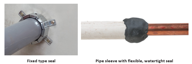
Pipe sleeve seals provide positive seals around pipe sleeves above or below ground to keep out debris, water, and pests.
Sealants used between and around the pipe and sleeve include:
- Flexible caulking
- Masonry mortar
- Mechanical elastomer seals
- Quick-setting bonding cement mixtures
- Pipe wraps
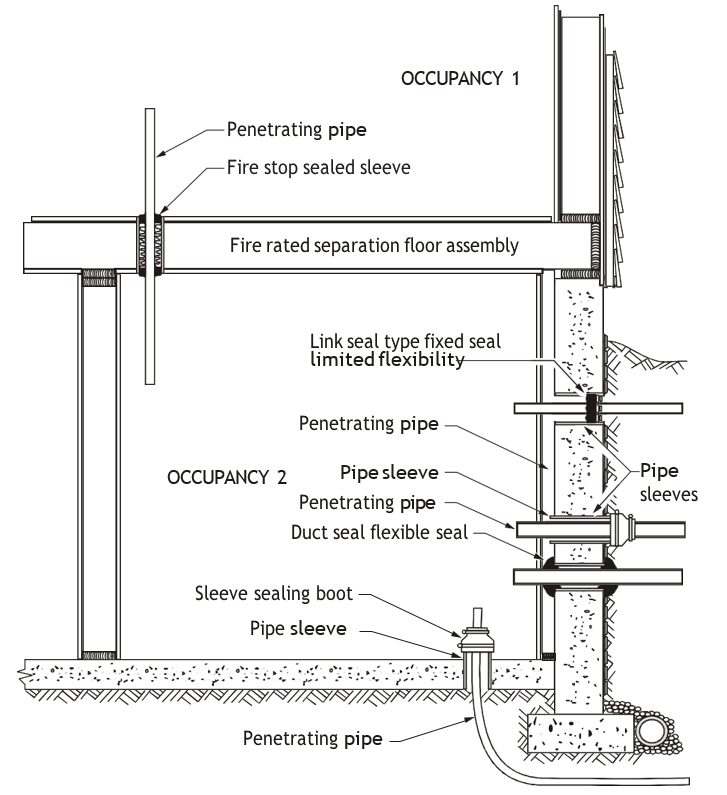
Figure 49 shows various applications of pipe sleeve seals.
Fixed Penetration Seals
Fixed penetration seals are suitable if flexibility is not needed. A fixed mechanical seal for general service can be made of EPDM (ethylene propylene-diene monomer), which is a synthetic rubber elastomer. Where the seal may come in contact with hydrocarbons, it may be made of nitrile. The pressure plates that hold the seal are generally made of glass-reinforced plastic
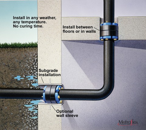
Flexible Penetration Seals
Flexible penetration seals are designed to close the pipe sleeve opening while allowing the pipe to move during operation. Flexible seals can absorb misalignments and angular penetrations.
Figure 51 shows a manufactured sleeve seal. This is a fast and economical way to seal a sleeve to a penetrating pipe. No other caulking is required.
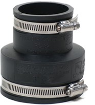
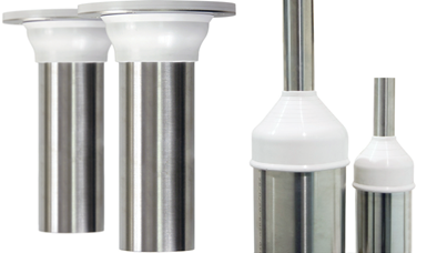
Figure 52 shows Pipetite sleeve boots designed specifically for sealing around tube-in-tube transitions. They provide good surface contact and eliminate the need for sealants, clamps or fasteners. Flexibility allows the pipes to move significantly without causing damage or breaking the seal. They also provide a finished look for exposed sleeves.
Sealing Below-Ground Pipe Penetrations and Isolating Groundwater
When pipes pass through foundations and slabs below ground level, unwanted moisture and vapour can enter the structure.
Problems caused by below-ground pipe penetration can include:
- Building and ground movement applying stress to the piping
- Moisture and water penetration
- Vapour penetration
- Expansion and contraction of piping and the foundation
- Corrosion of the piping
A properly placed pipe sleeve will help to avoid these problems. The pipe sleeve can allow some movement between the pipe and the foundation. The sleeve seal can reduce or prevent water penetration, and the application of a pipe wrap can prevent pipe corrosion and leakage through the penetration.
The methods of penetration and use of sleeves are supported by related codes and engineering practice. The following information is a summary only. Refer to each of the codes referenced for detailed requirements.
BC Plumbing Code Regulation
- Where piping passes through or under a wall it shall be installed so the wall does not bear on the pipe.
Gas Code Regulations
- Piping or tubing entering a building shall rise above grade before entry unless otherwise permitted by the authority having jurisdiction. (Gas piping should not enter the building from underground.)
- When gas piping is run in a sleeve, the sleeve shall be of such material and so installed as to protect the piping or tubing from damage and galvanic action.
- When gas piping or tubing passes through an exterior wall above ground, it shall be sealed watertight and the portion of piping that runs through the wall shall be sleeved or double wrapped with a waterproof wrap.
Fire Sprinkler Code
- Clearance shall be provided around all piping extending through walls, floors, platforms and foundations, including drains, fire department connections and other auxiliary piping.
- Unless other code requirements allow no clearance, where pipe passes through holes in platforms, foundations, walls or floors, the holes shall be sized such that the diameter of the holes is nominally 2 in. (50 mm) larger than the holes for pipe 1 in. (25 mm) nominal to 3 [latex]\frac{1}{2}[/latex]in. (90 mm) nominal, and 4 in. (100 mm) larger than the holes for pipe 4 in. (100 mm) nominal and larger.
- Where clearance is provided by a pipe sleeve, a nominal diameter 2 in. (50 mm) larger than the nominal diameter of the pipe shall be acceptable for pipe sizes 1 in. (25 mm) through 3 [latex]\frac{1}{2}[/latex] in. (90 mm), and the clearance provided by a pipe sleeve of nominal diameter 4 in. (100 mm) larger than the nominal diameter of the pipe shall be acceptable for pipe sizes 4 in. (100 mm) and larger.
Waterproof Pipe Wraps
When piping passes through a pipe sleeve, you must consider the type of materials the sleeve and the pipe are made from. For example, when a copper water line passes through a metal pipe sleeve, the following concerns arise:
- Contact between copper and a dissimilar metal
- Direct contact with the concrete
Contact between copper pipe and a steel pipe sleeve can result in damage to the copper pipe due to erosion caused by electrolysis. A plastic PVC or ABS sleeve can prevent damage caused when metal pipe contacts a pipe sleeve made of a dissimilar metal. Suitable pipe wraps can also be used.
Copper or any metal pipe that is going to be installed directly into concrete must be protected from contacting the concrete with a suitable pipe wrap or flexible continuous pipe sleeves.
Pipe wraps are mainly used to insulate, seal or protect piping from damage. Several manufacturers specialize in pipe wraps for specific jobs, including waterproofing, maintenance and sealing repairs. There are pipe wraps to suit just about any purpose, and there are many available for sealing and protecting pipe penetrations through concrete foundations. Procedures for applying these products vary; therefore you should read and follow the manufacturer’s installation procedures.
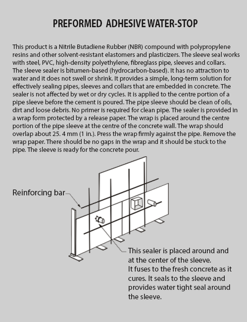
Following is a generic example of a manufacturer’s instructions for applying waterproof pipe wrap sealant.
Pipe Movement
The penetrating pipe is not likely to stay perfectly centred in the sleeve once backfill is placed over the pipe. The pipe can be pushed up against the sleeve wall. Any movement of the pipe against the sleeve can cause abrasions on the pipe. Continued movement caused by expansion and contraction or vibrations over time can cause the pipe wall to fail. The application of a pipe wrap is essential to prevent such damage.
Methods of keeping the pipe centred in a pipe sleeve include:
- Foam type insulation
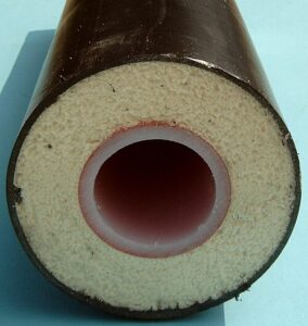
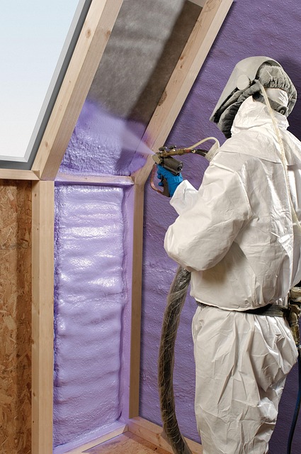
- Expanding spray foams
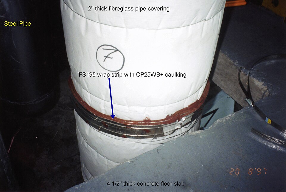
- Fibreglass pipe insulation
- Fabricated centring devices within the sleeve
- Proper support of the pipe independent of the pipe sleeve penetration
- Firestopping
If no sleeve is used, you will need to consider the effect of contact between the copper pipe and concrete or masonry mortar. Direct burial of a copper water line in concrete will cause the copper to corrode.
Sealing Around Boxed-Out Openings
Pipe penetrations through concrete walls including foundations can be boxed out before the concrete is poured or broken out after the concrete is poured. These boxed-out or broken-out holes are usually rectangular or irregularly shaped. Sealing a pipe penetration through a large, irregularly shaped hole becomes a challenge. The chance of finding a supplier of a manufactured seal to fit the hole is slim. If you are working on a job site, there may be a set of specifications and drawings with instructions for how to seal the pipe penetrations. You may also need to research manufacturers that make a product that will do the job.
Two examples of such products are Synko-Flex and Hydro-Flex waterstops, manufactured by the Henry Company. These provide a watertight seal in reinforced construction cold joints, cast-in-place applications, and through-wall penetrations.
Compatibility of Sealants and Pipe Materials
Pipe sealants such as pipe wraps and coatings can react with the piping they are intended to protect. PE and PEX have been known to let petroleum-based products to leach through the pipe walls and contaminate the water inside the pipe. Waterproofing emulsions form release agents and should not be allowed to contact this plastic pipe.
Firestop system manufacturers test firestop sealants and other components for compatibility with specific types of pipe. The sealants may not be compatible with every type of pipe material they come in contact with. Check with the manufacturer to ensure that the pipe sealants and wraps, including firestop sealant, are compatible with the type of pipe material being used.
 Self-Test D-4.1: Describe Factors Affecting Penetrations in Structures
Complete Self-Test 4.1 and check your answers.
If you are using a printed copy, please find Self-Test D-4.1 and Answer Key in the Appendix at the end. If you prefer, you can scan the QR code with your digital device to go directly to the interactive Self-Test.

References
BC Industry Training Authority. (2019). Piping trades apprenticeship program: Use Tools and Equipment—Level 1 harmonized [Binder]. Crown Publications, Queen’s Printer for British Columbia. https://www.crownpub.bc.ca/Product/Details/7960000261_S
- Describe factors affecting penetrations in structures
- Plumber: Competency D-6 Penetrate Structures
- Steamfitter: Competency D-3 Penetrate Structures
Henry Company. (n.d.). Synko-Flex waterstop. https://www.henry.com/commercial/products/waterstops/hydrophobic/synko-flex-waterstop/
Province of British Columbia. (2025). BC Building Code 2024. Government of British Columbia. https://www2.gov.bc.ca/gov/content/industry/construction-industry/building-codes-standards/bc-codes/2024-bc-codes#2024
Media Attributions
All figures are sourced from Industry Training Authority (2019) and/or Camosun College (2019) and are used under the Creative Commons Attribution 4.0 (CC BY 4.0) licence unless otherwise noted. Images copyrighted by the BC Industry Training Authority are licensed under a Creative Commons Attribution-NonCommercial-ShareAlike 4.0 (CC BY-NC-SA 4.0) licence.
- Figure 22 Wood roof truss, by Sgt. Nicholas Olson of the United States Army (ID 100713-A-5170O-167) from Wikimedia Commons, is in the public domain.
- Figure 54 PMR 63×5.8 125 file2 by Sönke Kraft [aka Arnulf zu Linden] from Wikimedia Commons is used under a CC BY-SA 3.0 license.
- Figure 55 Insulation by justynkalp from Pixabay is used under the Pixabay Content License.
- Figure 56 Fiberglass pipe covering [Fs195 cp25 fibreglass pc] by Achim Hering from Wikimedia Commons has been released into the public domain by its author.
The ability of a building or structure to remain strong, stable, and safe under loads without failure or damage. (Section D-4.1)
A part of a building that supports loads or contributes to the strength and stability of the structure, such as beams, columns, walls, floors, and foundations. (Section D-4.1)
A material or system that prevents air movement through a building structure. (Section D-4.1)
A construction assembly designed to resist the spread of fire. (Section D-4.1)
A construction system designed to resist fire for a specified period of time. (Section D-4.1)
The length of time that a building component or assembly can resist the spread of fire while maintaining its structural integrity, usually measured in minutes or hours. (Section D-4.1)
A fire-resistant wall that separates buildings or sections of a building. (Section D-4.1)
A shared wall between two adjoining buildings or units that acts as a fire separation and may also provide sound insulation. (Section D-4.1)
(Also called glulam and paralam); An engineered wood beam made by bonding together layers of lumber with adhesive to create a strong, stable structural member. (Section D-4.1)
A material installed to prevent the spread of fire through concealed spaces. (Section D-4.1)
(Also called I-beam); A lightweight engineered wood beam shaped like the letter “I,” commonly used in floors and roofs. (Section D-4.1)
A section of a structural beam where stress is highest and drilling is restricted. (Section D-4.1)
The movement of sound through building materials or structures. (Section D-4.1)
A device used to reduce the transfer of vibration and noise between components. (Section D-4.1)
A material installed to prevent water penetration at roof or wall openings. (Section D-4.1)
A protective cover placed over a pipe penetration on a roof, used with flashing to prevent water from entering around the pipe. (Section D-4.1)
A structural framework made of steel members designed to support loads in roofs or floors, typically engineered for strength, stability, and efficient load distribution. (Section D-4.1)
Corrugated steel panels used as a structural base for floors or roofs, often supporting concrete or roofing materials and providing strength and stability to the structure. (Section D-4.1)
A protective insert used to prevent damage to pipes passing through metal or other materials. (Section D-4.1)
A reinforced horizontal element in a masonry wall that strengthens and ties the wall together. (Section D-4.1)
Steel bars embedded in concrete to provide strength and support. (Section D-4.1)
Adjustable steel support posts used to temporarily support structures such as formwork or beams during construction, allowing height to be changed as needed. (Section D-4.1)
An opening intentionally formed in concrete or other structural components during construction to allow space for pipes, ducts, or other services to be installed later. (Section D-4.1)
A concrete slab reinforced with tensioned steel cables to increase strength and reduce cracking. (Section D-4.1)
A steel cable used in post-tension concrete to apply compressive force. (Section D-4.1)
A method of drilling circular holes in concrete using a specialized drill. (Section D-4.1)
A protective tube that allows a pipe to pass through a structure safely; also refers to protective pipe or tubing that surrounds a pipe carrying the fluid to be used. (Section D-4.1)
Temporary structures used to shape and support concrete until it hardens. (Section D-4.1)
The process of installing pipe sleeves in formwork before concrete is poured. (Section D-4.1)
A fastening device used to secure pipe sleeves to formwork or structural surfaces. (Section D-4.1)
A sealing device used to close the gap between a pipe and a pipe sleeve. (Section D-4.1)
A seal that closes a pipe sleeve opening while allowing pipe movement and absorbing misalignment, maintaining a watertight, airtight, or fire-resistant seal. (Section D-4.1)
Flexible, pre-manufactured seals designed to fit around pipes passing through walls or floors, providing a watertight and durable seal without the need for additional sealants or fasteners. (Section D-4.1)
Material, such as soil or gravel, placed back into an excavation around a pipe or structure to provide support and restore the ground surface. (Section D-4.1)
A material used to prevent water from passing through joints in concrete. (Section D-4.1)