D-3.1 Describe Fittings Used in the Pipe Trades
Fittings Terminology
The terminology used to identify fittings may include all or some of the following information:
- Fitting size
- Material the fitting is made from (e.g. cast iron, copper, ABS, etc.)
- Intended use for the fitting (pressure or drainage, etc.)
- Basic shape of the fitting (tee, elbow, wye, etc.)
- Joint type (soldered, threaded, solvent cement, etc.)
As you proceed through this section, you will learn to use all of these characteristics to identify and name fittings.
Abbreviations Used to Identify Fittings
Abbreviations are used throughout the industry to reduce the amount of writing needed to identify fittings. Pipe tradespersons use abbreviations when compiling material takeoff lists. Abbreviations may vary depending on the manufacturer and local practices. These differences can cause errors when interpreting a material list. If you do not know the correct abbreviation, write out the full word.
Incorrect use of an abbreviation may result in a wrong fitting being priced and shipped to the job site. Abbreviations should be clearly written, and both the writer and the reader should be able to interpret the abbreviation correctly.
Table 1 lists some common abbreviations used in the pipe trades. You must memorize these common abbreviations, and be able to interpret and write them. Be aware that the table does not show all possible abbreviations.
|
Abbreviation |
Meaning |
|
Adpt |
Adapter |
|
Blk CI |
Black cast iron (threaded pipe fittings) |
|
Blk mal |
Black malleable (threaded pipe and fittings not galvanized) |
|
C×C |
Copper by copper (pipe and fittings) |
|
C×FIPT |
Copper by female iron pipe thread |
|
c/o |
Clean out |
|
CB |
Cast brass; also catch basin |
|
CI |
Cast iron (pipe and fittings) |
|
CSA |
Canadian Standards Association. Note: All fittings and pipe used in the plumbing system must be CSA approved for the application for which they are used. |
|
Dbl |
Double (e.g. double wye) |
|
90 degree ell |
90 degree elbow |
|
DWV |
Drainage waste and vent fittings and pipe |
|
Fit.C×FIPT |
Fitting copper by female iron pipe thread |
|
Galv |
Galvanized (pipe and fittings with a zinc coating for corrosion resistance) |
|
IPS |
Iron pipe size |
|
IPT |
Internal pipe thread, or iron pipe thread |
|
F or M |
Female or male |
|
FPT |
Female pipe thread |
|
FIPT |
Female iron pipe thread |
|
JIC |
Joint Industry Conference |
|
Mal |
Malleable (pipe and fittings) |
|
MJ |
Mechanical joint clamp (pipe and fittings) |
|
MIP, MPT, or MIPT |
Male iron pipe, male pipe thread or male iron pipe thread |
|
OPT |
Outside pipe thread |
|
RH or LH |
RH = right hand; LH = left hand (used when identifying the location of the side outlet on a DWV fitting) |
|
S |
Solvent cement ABS and PVC socket fitting joint |
|
SAE |
Society of Automotive Engineers |
|
San |
Sanitary (drainage fittings) |
|
Sch |
Schedule (used to describe a steel pipe wall thickness) |
|
SO |
Side outlet (used to describe a tee with a side outlet connection) |
|
SP |
Spigot end |
|
Tapt |
tapped (refers to fitting openings that are threaded to accept MIP threads) |
|
w/o |
without (e.g. an ABS P trap w/o cleanout) |
|
WB |
Wingback |
|
WC |
Water closet |
|
WOG |
Water, oil, gas |
|
SWOG |
Steam, water, oil, gas |
|
Wrot |
Wrought |
|
Wye |
Y fitting |
Abbreviations Exercise
Complete Table 2 from memory if possible. Then refer to Table 1 and other sources to check your answers and find any missing abbreviations.
|
Abbreviation |
Meaning |
|
ell |
|
|
|
Adapter |
|
|
Black cast iron (threaded pipe fittings) |
|
|
Black malleable (threaded pipe and fittings, not galvanized) |
|
C×C |
|
|
C×FIPT |
|
|
c/o |
|
|
|
Cast iron (pipe and fittings) |
|
CSA |
|
|
Dbl |
Double (e.g. double wye) |
|
DWV |
|
|
FIPT |
|
|
Galv |
|
|
IPS |
|
|
IPT |
|
|
FPT or FIPT |
|
|
|
Malleable (pipe and fittings) |
|
|
Mechanical joint clamp (pipe and fittings) |
|
OPT and MPT |
|
|
RH or LH |
|
|
MIPT |
|
|
SAE |
|
|
|
Sanitary (drainage fittings) |
|
|
Schedule (used to describe a steel pipe wall thickness) |
|
|
Side outlet (used to describe a tee with a side outlet connection) |
|
|
Spigot end |
|
Tapt |
|
|
|
without (e.g. an ABS P-trap w/o cleanout) |
|
WC |
|
|
WB |
|
|
WOG |
|
|
|
Wrought |
|
|
Y fitting |
Types of Fitting Applications
Fittings are commonly separated into two basic application types:
- Pressure fittings (used to carry fluids under pressure)
- DWV fittings (used to carry fluids by gravity; drainage, waste, and venting)
Differences Between DWV and Pressure Fittings
Plumbing fittings are often identified by application and shape. There are four main differences between DWV fittings and pressure fittings. You should be able to note these differences and identify, from a selection of fittings, which fittings are for pressure applications and which fittings are for DWV applications.
The four main differences between pressure and DWV fittings are:
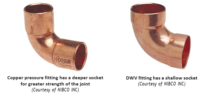
- Pressure fittings have an abrupt turn radius at the throat of the fitting, while the DWV fitting has a gradual change in direction.
- The socket end of pressure fittings are usually much deeper, providing greater joint strength than DWV fitting joints.
- DWV fittings have a recessed interior surface. When the inside surfaces are aligned, flow is smoother and blockages are reduced. All DWV fittings have this recess.
- Copper pressure fittings may have thicker walls than DWV fittings.
Test Yourself
You must be able to identify fittings correctly when making a material takeoff list. As you go through this module, cover the fitting descriptions and write out the correct identification of each fitting. Remember, one of your objectives is to be able to visually name and identify pipe fittings.
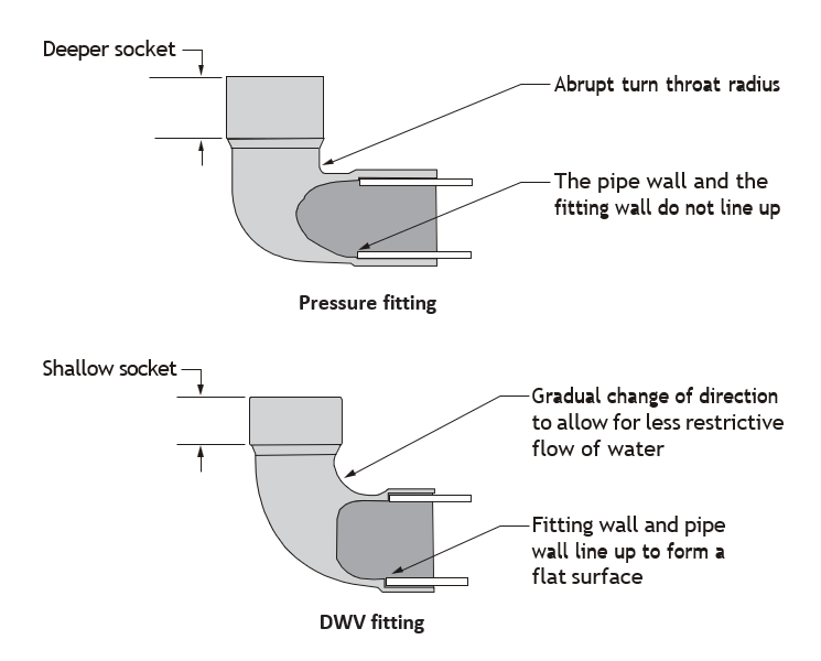
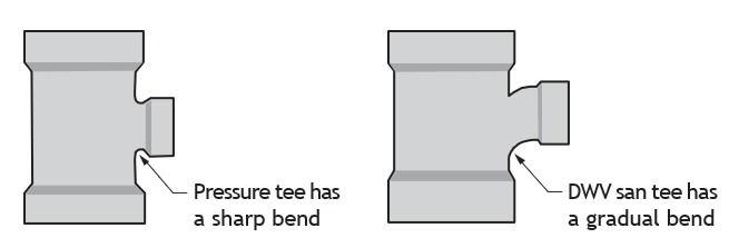
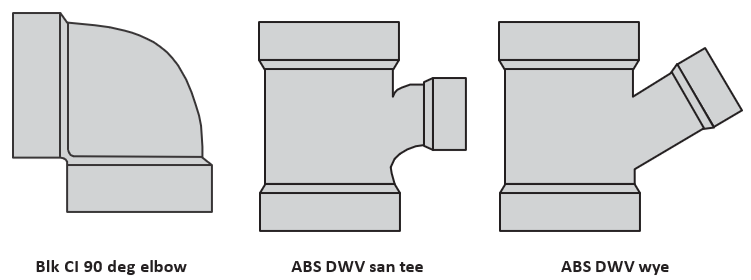
Fittings used for pressure applications should not be interchanged with those for drainage, waste, and vent purposes (DWV systems). Although the basic shapes and sizes may be the same, the specific design of each is different. An important feature to remember when you are trying to identify fittings is that DWV fittings have more gradual bends to direct the flow (Figure 2).
Basic Parts of Fittings
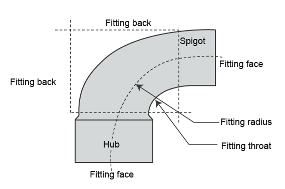
Pipe tradespersons must be able to identify the basic parts of fittings to measure and install them correctly. For example, plumbing codes require that 4″ diameter (10 cm) or less than 90 degree elbows have a centreline radius of not less than their diameter. To interpret the code, the pipe tradesperson must be able to identify where the radius and the centreline are located. Similarly, when installing pipe, tube, and fittings, a tradesperson must be able to identify the parts of fittings in order to accurately measure them.
The basic parts of a fitting include:
- Throat
- Radius
- Hub end (also referred to as the socket or bell end)
- Spigot end (the end of a fitting or pipe that has no hub: fits into the hub end of another fitting or pipe)
- Centreline (an imaginary line along the centre of pipes and fittings)
- Face (also referred to as front; generally used to refer to a flange face)
- Back (the back of the fitting)
Considerations When Selecting Fittings
Pressure Ratings
System pressure is an important factor when selecting fittings. Piping system pressures can vary from atmospheric pressure to several thousand kilopascals (kPa), or pounds per square inch (psi). Fittings must be designed and made from materials that can withstand these pressures. You will learn later how pressure ratings are also used when describing fittings.
Wrought (Wrot) Copper Compared to Cast Brass
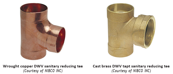
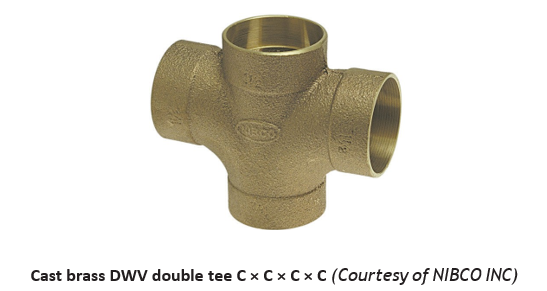
Fittings for copper piping can be made of wrought copper or cast brass. Wrought copper fittings, sometimes referred to as streamline fittings, have the same colour, smooth texture and malleability as copper pipe. Cast brass fittings have a rougher texture and a brass-coloured appearance, and are not as malleable as copper. These differences may be a concern when selecting a fitting: cast brass fittings manufactured for use in DWV and potable water systems may not be suitable for high temperature brazing. Industrial-grade cast brass fittings can be used for high-temperature brazing.
Figure 4 shows wrought copper and cast brass fittings for various applications. Figure 5 show examples of copper and brass fittings.
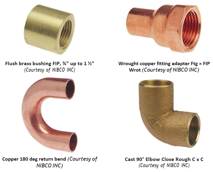
A wrought copper solder pressure female adapter is used in residential and commercial systems such as potable water, air conditioning and refrigeration. Options also include cleaned and bagged for medical gas applications.
Malleable Iron vs Cast Iron Threaded Fittings
| Cast Iron | Malleable Iron |
| Cast iron fittings have a larger bead than malleable iron fittings. Recall that the term bead is used to describe thickening on a threaded fitting, to provide strength at the point of the thread connection. The thick bead is required for strength. | Malleable fittings resist cracking due to their malleability. |
| Cast iron fittings will crack if subjected to excessive stress, such as over-tightening. | Malleable iron fittings are stronger and will stretch rather than crack under normal installation. The size of the bead is therefore smaller than a cast iron fitting bead. |
| Cast iron fittings have a greater chance of containing sand holes produced at the time of manufacture. | Malleable iron fittings are typically used in gas piping systems. |
| Cast iron fittings can crack and are unsuitable for gas piping. | |
| Cast iron pattern threaded fittings may be used in hot water (hydronic) space heating systems. |
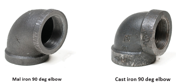
Both types of fittings are used in piping systems. Always check the job specifications and local codes to determine the correct application.
Threaded fittings are also available in brass for use in potable water systems, and forged steel for use in high-pressure fluid systems such as steam and hydraulic systems.
Types of Fittings
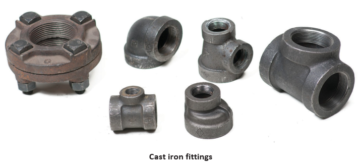
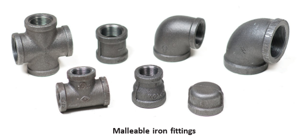
Figures 7 show examples of fittings in the three basic categories: elbows, tees, and specialty fittings. Notice that the size designations have not been included. Sizing identification will be included later in this section.
- Elbows (bends)
- Tees, double tees (crosses), wyes, double wyes
- Specialty fittings (fittings that do not fit into the first two groups), including:
▸ Couplings and unions
▸ Adapters
▸ Bushings and reducers
▸ Caps, plugs and cleanouts
▸ Traps and continuous waste fittings
Elbows
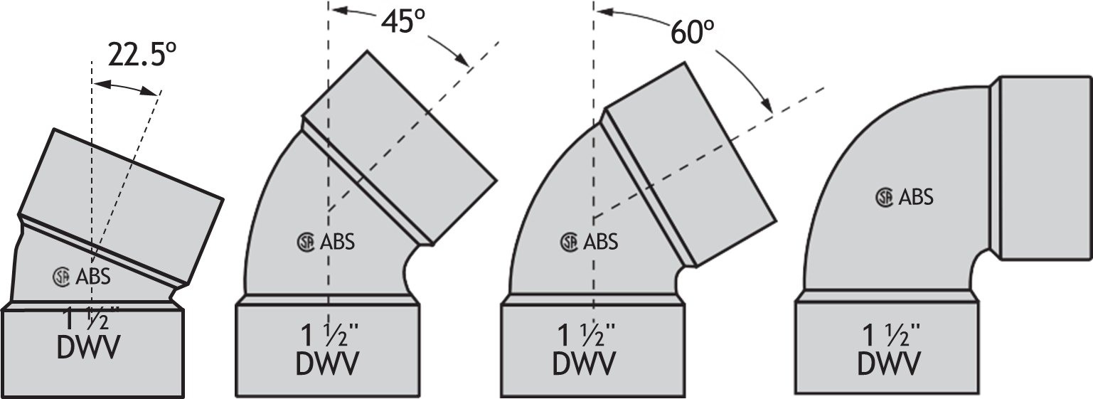
Pipe tradespersons use the term elbow to describe fittings that change the direction of a pipeline.
Common angles include:
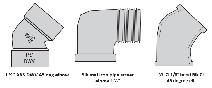
- 22½°
- 45°
- 60°
- 90°
Other angles can be obtained from the manufacturer, or in some cases the elbow may be fabricated on the job site. Fabrication of fittings is more closely related to the job of a steamfitter. Plumbers would normally purchase elbows with the standard changes of direction. Experienced pipe tradespersons can correctly identify the angle of a fitting just by looking at it.
Standard radius elbows and long radius elbows are also manufactured. Long radius can also be referred to as long sweep. Manufacturers sometimes use the terms short radius, long radius and standard turn to describe the different radii of their elbows. Some elbows are available with a 180 degrees change of direction. These are called return bends.
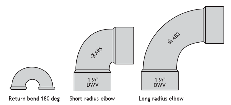
Fittings often include printing that indicates the size, use, and type of material from which the fittings are made. Also notice the Canadian Standards Association (CSA) stamp of approval.
Street Elbows
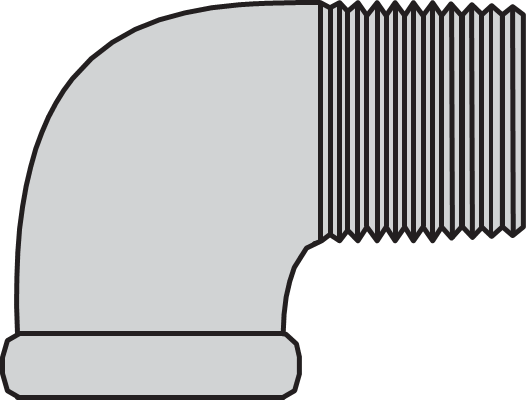
A street elbow is an elbow with outside threads on one end (MIP) and inside threads on the other (FIP). The name street elbow derives from its use on water mains and services located on the street.
Exercise
Reducing Elbow
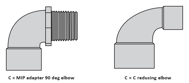
Elbows can be used to reduce the size of piping and at the same time change direction. These elbows are called reducing elbows. An elbow can also be used as an adapter, as shown here:
Bends
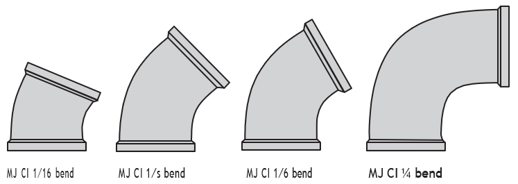
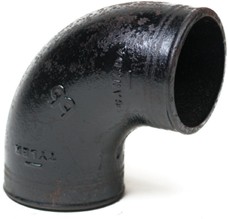
The term bend may also be used to describe an elbow. For example, cast iron DWV fittings are traditionally referred to as bends instead of elbows. A plumber would therefore refer to a 90 degree cast iron DWV elbow as a 1/4 bend. The 1/4 refers to 1/4 of a 360-degree circle. Cast iron DWV elbows are available in 1/4, 1/6, 1/8 and 1/16 bends.
Following are the equivalent degrees of cast iron DWV bends:
- A 1/16 bend is equal to a 22[latex]\frac{1}{2} \text{"}[/latex] degree elbow.
- A 1/8 bend is equal to a 45 degree elbow.
- A 1/6 bend is equal to a 60 degree elbow.
- A 1/4 bend is equal to a 90 degree elbow.
Specialty Elbows
Some elbows are manufactured to serve a specific purpose in addition to allowing a change of direction. One such elbow is called a wingback elbow. A wingback elbow may be used to provide support for the piping in the wall behind showerheads and fixture water supply piping. The wingback elbow has two lugs that allow it to be fastened to backing. The wingback elbow is known by several other names, including:
- Lug ear elbow
- Drop-ear elbow
- Drop elbow
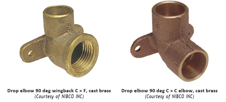
A variation of the copper by copper wingback 90 degrees is the copper by female iron pipe wingback 90 deg, which is often used to secure the stub-out for a showerhead.
Tees, Wyes, and Double Sanitary Tees (Crosses)
Pipe tradespersons refer to fittings that allow three pipes to be joined together as tees and wyes. Tees are shaped similar to the letter “T,” and wyes are shaped similar to the letter “Y.”
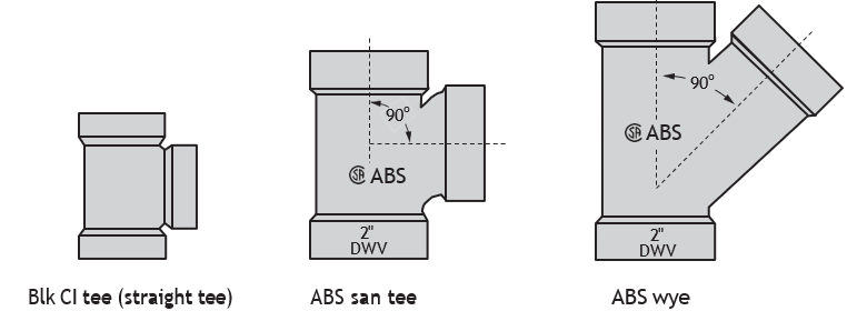
Straight Tees, Sanitary (San) Tees and Wyes
Straight tees and san tees are used to connect two pipes together at an angle of 90 degrees.
A standard wye designed for DWV use connects one pipe to another at a standard angle of 45 degrees.
Plumbers will purchase DWV wyes with the standard 45-degree angle. A steamfitter, however, may be required to fabricate a wye at a different angle.
Double Sanitary Tee and Double Wyes
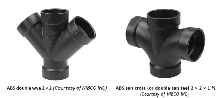
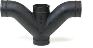
Sanitarycross (doublesanitarytee) and double wye are the names given to fittings that allow four pipes to be joined together. The name cross comes from its shape. Plumbers use the terms san cross and double san tee interchangeably.
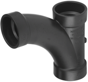
A tee wye is a sanitary tee with a longer radius throat. On the job today the sanitary tee has become the fitting of common use and the true tee wye is used less and less.
Reducing Tees and Wyes
Tees, wyes and crosses can also be used to connect pipelines of different sizes. These fittings are called reducing fittings (Figure 20).
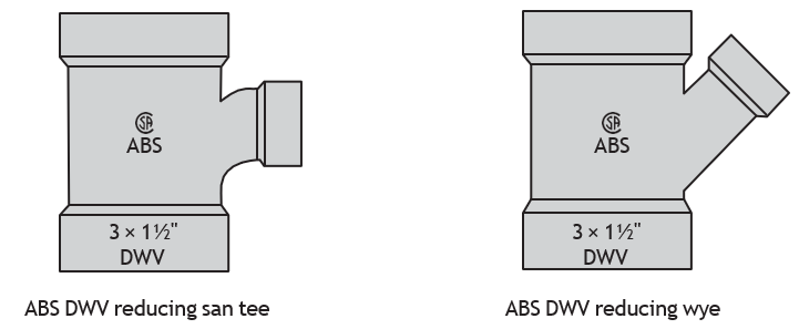
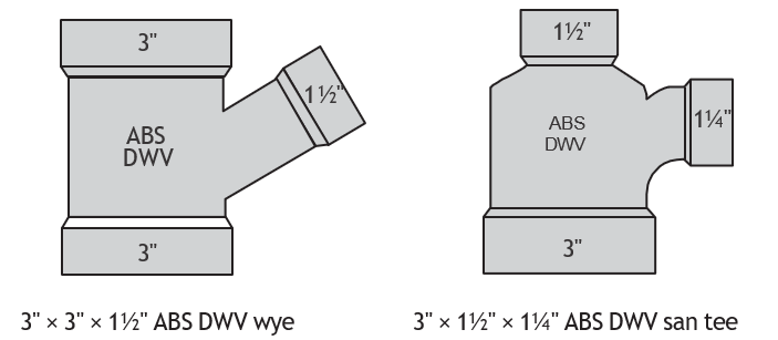
Note: When naming a fitting such as these reducing fittings, the term reducing might not be used in the description. The fitting would instead be called a 2″ × 1 [latex]\frac{1}{2} \text{"}[/latex] ABS DWV san tee. Stating the fitting opening sizes with the largest opening first indicates that the tee is a reducing tee.
Specialty Tees and Wyes
Manufacturers have produced variations of tees, crosses, and wyes for use in specific plumbing installations.
Side Inlet and Tapped Fittings
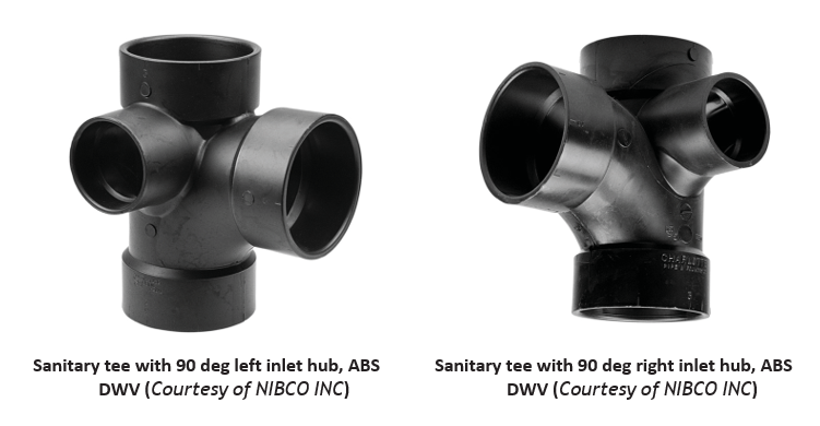
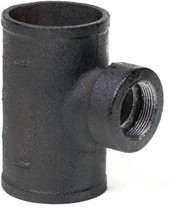
A side inlet tee is a standard sanitary tee with an additional opening located on the right-hand or left-hand side. Side inlet fittings can have more than one opening on the side. The side inlet is usually located at 90 degrees to the branch opening but may also be 45 degrees to the branch opening.
Tapped (Tapt) Internal Pipe Thread Fitting Openings
Cast iron DWV fittings are often tapped to allow for adaptation to other pipe materials such as copper or ABS. The opening is referred to as a tapt opening, and so the fitting is described as a tapt side outlet.
Note: Fitting side outlets are not always tapped.
Other types of specialized wyes and tees include Boston (a wye and 1/8 bend combination in one fitting), upright wye, and apartment tees.
Specialty Fittings
Couplings
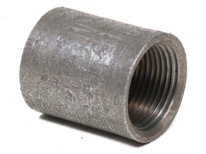
Couplings are loosely defined as short fittings that are used to join piping in a straight line without changing its direction. Couplings generally have socket-type ends and may be screwed, soldered or solvent-cemented onto piping. Malleable iron or steel couplings are usually available with internal iron pipe threads; plastic couplings may have slip-type or FIPT ends.
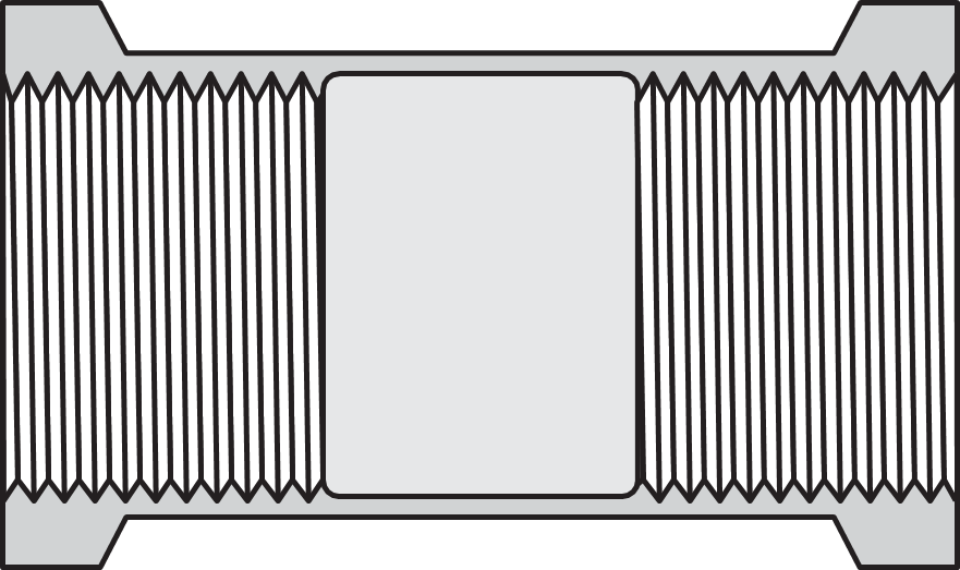
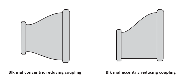
Standard and Reducing Threaded Couplings
Standard couplings are used to join pipes that are the same size. Reducing couplings can be used to connect different sizes of piping. Figures 24 and 25 show couplings used to connect threaded pipes. Couplings are also available to connect other piping, including ABS and PVC.
Merchant Couplings
Merchant couplings are often used to protect pipe threads during transportation. They are not generally used for pressure piping. Couplings [latex]\frac{1}{8}[/latex] to 2 in. are straight threads, and 2 [latex]\frac{1}{2} \text{"}[/latex] in. and larger diameter are NPT (tapered).
Couplings for Copper Tube
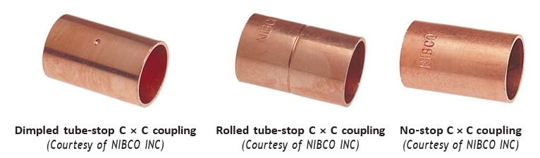
Copper tube couplings are available with or without internal stops. The internal stops are located at the centre of the fitting. The stop prevents the tubing from being pushed into the coupling past the centrepoint of the coupling. This ensures that each pipe is soldered at the correct depth in the socket.

Practical Use for No-Stop Coupling
Perhaps a less familiar fitting, let’s take a look at its installation.
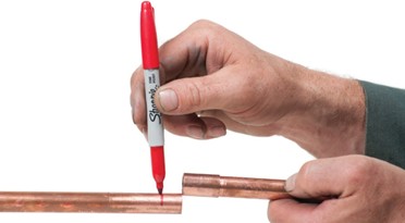
A no-stop coupling can be used to advantage when repairing or altering a pipeline. As described in the steps below, pipe ends that cannot be pulled apart far enough to allow a fitting to be installed, could be spread sideways and a no-stop coupling slid all the way over the end of one pipe.
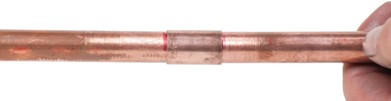
The pipe can then be realigned and the coupling slid back from one pipe over the other until the coupling is centred on both pipes. Mark the pipe with a line to help determine where to position the coupling.
Note: Proper cleaning and fluxing of the joint surfaces before assembly and soldering is required.
Step 1. Pull one pipe end to one side.
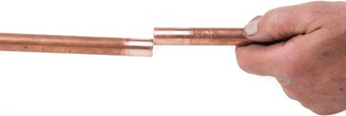
Step 2. Slide the no-stop coupling over one end of the pipe.
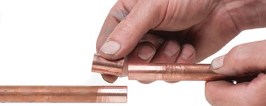
Step 3. Mark the pipe.
Step 4. Realign the two pipes.
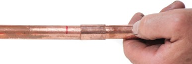
Step 5. Slide the no-stop coupling back to the mark on the pipe.
Unions
Unions allow piping to be assembled and equipment to be installed so the piping or equipment can be easily removed and reconnected if necessary.
Standard pipe threads are normally right-hand thread; therefore, connections must be turned in a clockwise direction to tighten. A union allows piping to be tightened into a stationary fixture such as a boiler.
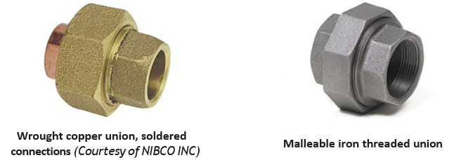
A union has three parts, two of which are screwed or solvent-welded to a pipe. The third piece is a threaded hexagonal nut, collar, or ring to hold the union together.
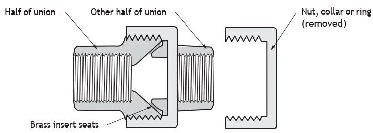
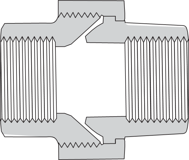
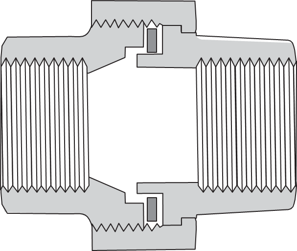
There are two types of threaded unions:
Ground unions may have iron-to-iron or brass insert seats with a tapered design. The tapered seat union forms a watertight seal without a gasket.
Gasket unions require a washer between the two fitting pieces to seal the joint. The two fitting pieces have flat seats that provide a watertight seal when used with the washer.
Adapter Fittings
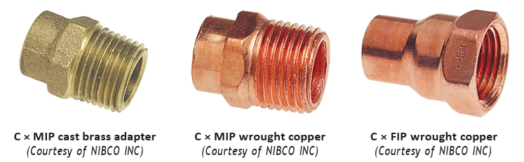
Adapters are fittings used to connect sections of piping that have different jointing designs. Adapters may be used to connect copper pipe to iron pipe threads. Adapters are sometimes called transition fittings. Some manufacturers identify any fitting that joins threaded pipe to soldered or welded pipe as an adapter.
Bushings and Reducers
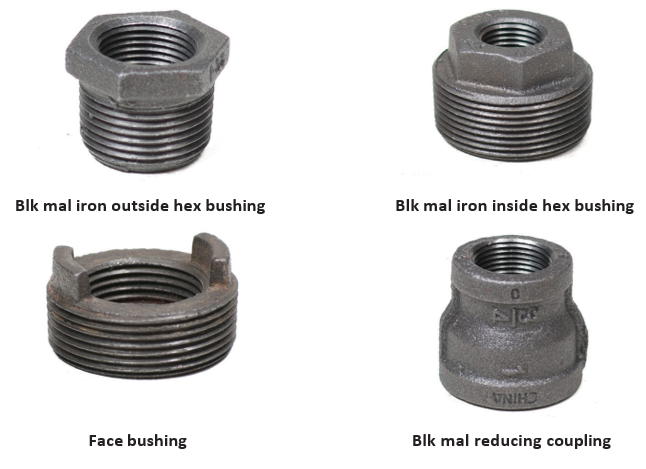
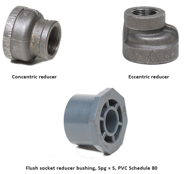
Bushings and reducers are used to connect different sizes of piping or fittings in a straight line. Bushings generally have inside- and outside-threaded ends and are used to connect smaller piping to larger fittings or fixtures. An MJ cast iron fitting that changes a pipe size is called a reducer or increaser.
Figures 38 show examples of bushings and reducers.
Caps and Plugs
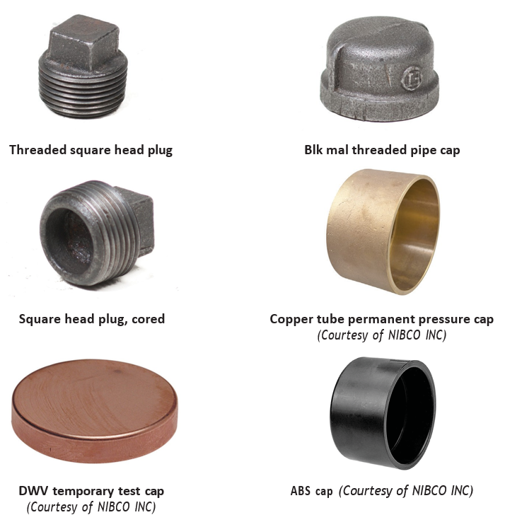
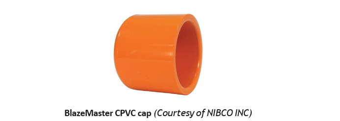
Caps and plugs are used to seal the ends of pipes. Caps are fittings with internal threads that screw onto the end of a pipe. Caps are also available for other piping materials such as ABS and copper. A plug is a fitting with external threads and a square head or square socket head. Plugs can be easily installed and removed with a wrench.
Figures 39 show various types of caps and plugs.
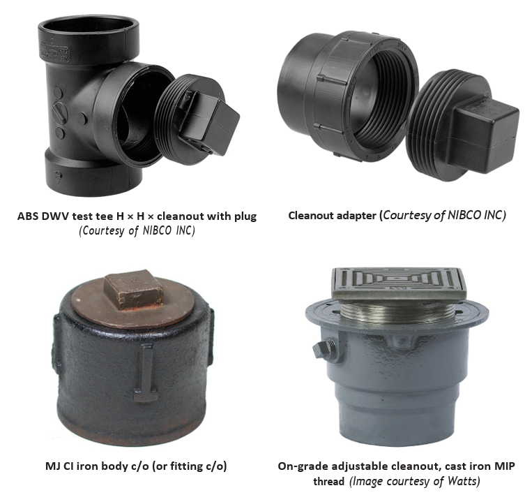
Cleanouts
Cleanout openings are provided to allow access to DWV pipelines to clear blockages.
Factors Used in Describing Fittings
Manufacturers identify fittings by some or all of the following seven factors:
- Size
- Material (e.g. cast iron, copper, ABS, pipe schedule, etc.)
- Intended use (pressure, drainage, etc.)
- Basic shape (tee, elbow, wye, etc.)
- Type of joint (soldered, threaded, solvent cement, compression, flared, slip joint, etc.)
- Other components/information (e.g. hub end, spigot end, drop ear, with cleanout, without cleanout)
- Class designation: manufacturers often designate their fittings as classes to indicate the maximum pressure and temperature ratings the fitting can withstand; for example, cast iron threaded fittings include classes 125 and 250. This indicates a maximum of 125 psi (862 kPa) saturated steam and 250 psi (1724 kPa) saturated steam, respectively. Other rating classes include 150- and 300-pound malleable class fittings.
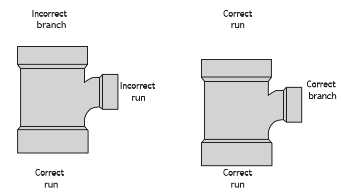
Identifying Run and Branch
When identifying the size of fitting openings, you must start by first determining the run size. You must therefore be able to identify which openings make up the run and which opening is the branch (also called the lateral). Figure 41 illustrates how to correctly identify the run and the branch.
Side Inlet Connections
A tee with an additional opening on its side is identified as a side inlet fitting. A tee with a side inlet can be identified as right hand or left hand by looking at the tee with the branch facing you (Figure 43), and checking which side the inlet is on. If it is on your right, it is a right-hand side inlet fitting. If the outlet is on the left, it is a left-hand side inlet fitting.
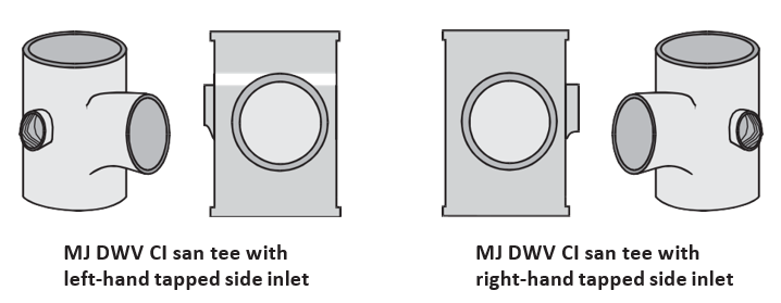
Note: The side inlet is called a tapped side inlet. Tapped indicates that the side inlet is threaded internally. The tapped inlet allows the installation of an adapter to connect to another type of piping material such as copper or ABS.
Rules for Describing a Fitting
Descriptions of fittings are written in a set order and following specific rules. The order of the information is as follows (Figure 44):
- Size
- Material type
- Use
- Shape
- Joint method
- Additional information, if required
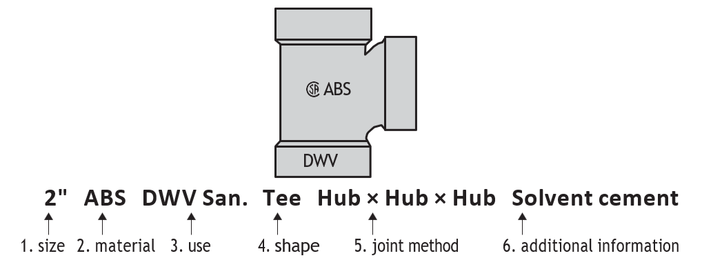
In Figure 44, since all the openings are the same size, only one opening size need be stated. (Refer to the fitting description guidelines below.) Also, fitting description numbers 5 and 6 are both optional because the material description (ABS) indicates that solvent cement and hub-type ends are typical (for ABS fittings). If the fitting was anything other than a standard ABS fitting, you may have to include the additional descriptions. Some ABS fittings, for example, may have spigot ends or threaded ends; those ends would have to be identified. You will identify these types of fittings later in this section.
Basic Rules for Fitting Descriptions
When writing a fitting description, observe the following rules:
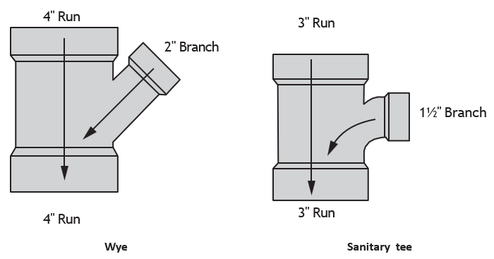
- Start the size description with the largest size run first, then the smallest size run, followed by the branch size last.
- Only one size description is needed when all the openings of the fitting are the same size.
- The jointing method may be obvious from the material type description. Therefore the jointing method may not have to be stated. For example, the material description ABS DWV would normally indicate a solvent cement joint, so there would be no need to mention solvent cement in your fitting description.
- Start with the opening that will be the furthest downstream.
- Specialty fittings with odd connections may require a more detailed description, or you may have to change the order of your description. Remember, be accurate and concise in your description.
Describing a Reducing Fitting
Correctly describing the sizes of the openings is of prime importance when you are identifying a fitting. Figure 45 illustrates the correct way to identify the openings of a reducing wye and a reducing tee.
Describing a Sanitary Cross or Double Sanitary Tee and Wye
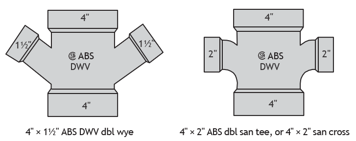
Figure 46 illustrates how to describe a DWV cross (also called double sanitary tee) and an ABS double wye. Note that only two sizes are stated in each fitting even though there are four openings. There is no need to repeat the sizes when the run stays the same size or the branches are the same size. Furthermore, fittings that have several openings that are all the same size can be described by one dimension.
Describing a Bullhead Tee
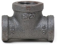
Although most fitting descriptions list the largest size opening first, this is not always the case. In the case of a bullhead tee configuration, the openings on the run of the tee are smaller than the branch opening, so the largest opening is listed last.
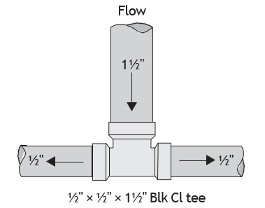
In Figure 47, notice that the flow is supplied through the branch. When you describe the fitting, however, you must follow the rules and start with the run first, regardless of the flow direction. Do not start your fitting description with the largest opening when describing a bullhead tee.
Describing a Plumbing Trap
A plumbing trap (abbreviated as P-trap) is a type of specialty fitting used to connect plumbing fixtures to the plumbing drainage system. P-traps are available in several design types and can be made from different materials. Figure 49 illustrates how to describe traps.
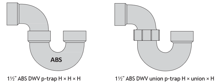
You can see from the plumbing trap descriptions in Figure 49 that you need to include additional information. The size, material, and use do not provide enough information to give a full description.
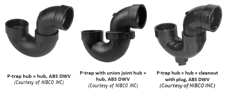
Examples of ABS Trap Types
Figure 50 show various types of ABS traps.
Describing Pipe Nipples
A pipe nipple is a short piece of threaded piping up to 300 mm (12 in.) long. Pipe nipples are available in standard IPS diameters and may be made from any threadable piping such as black iron, galvanized steel, brass, or PVC. Nipples are used to assemble piping projects where fittings are close together or in tight spaces. Pipe tradespersons would normally purchase a variety of nipples rather than thread their own nipples on the job. In most cases, it is more economical to purchase pipe nipples. Plumbing companies with threading equipment may find it more economical to thread all their pipe nipples on the job.
Pipe tradespersons purchasing nipples commonly purchase threaded pipe nipples up to 2 in. diameter and 150 mm (6 in) long; longer pipe nipples are threaded on the job. Pipe nipples over 2″ diameter are usually purchased.
There are three common types of nipples:
- Close nipple
- Shoulder nipple
- Long nipple
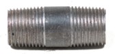
A close nipple is a short piece of pipe, threaded from each end so that it appears as though the entire outer surface is threaded.
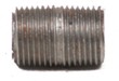
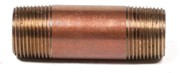
A shoulder (short) nipple has a short space between the threads at either end.
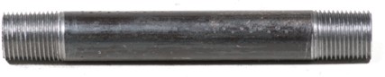
A long nipple has the same number of threads as a shoulder nipple, but is available in a range of lengths from 5–60 cm (2–12 in).
Methods of Joining Pipe and Fittings
There are several methods of joining piping and fittings, and new methods are continually being developed. Pipe tradespersons must be familiar with many methods of joining pipe and fittings.
When describing a fitting, you must indicate what joint method is to be used. A [latex]\frac{1}{2}[/latex] inch elbow, for example, could be soldered, threaded, flared, or crimped, so you would need to include the joint type in the fitting description.
Some of the common joining methods are as follows:
- Soldered fittings (also referred to as sweat fittings), used for joining copper tube
- Threaded fittings, used for joining steel pipe, including stainless steels and brass pipe
- Flanged fittings, used for joining steel pipe and many other pipe material types
- Welded fittings, used for joining steel pipe, including stainless steel
- MJ clamp fittings, used for joining cast iron DWV pipe and several other pipe materials
- Flared fittings, used for joining copper tube and other pipe materials
- Compression fittings, used for joining copper tube and several other pipe materials
- Fusion welded fittings, used for joining plastics such as polyethylene gas pipe
- Solvent cement fittings, used for joining ABS and PVC pipe
- Crimped fittings, used for joining polyethylene and polybutylene pipe
- Grooved fittings, used to join steel pipe, copper and ductile iron
- Brazed fittings, used to join copper or brass
- Push-on fittings, used for water main piping
Note: Variations of these joining methods are used throughout the pipe trades.
Soldered Fittings (Sweat)
Soldered fittings (sweat) and brazed fittings are often used to install potable (safe for human consumption) water systems, drainage systems and other systems where soldered or brazed joints are acceptable. Soldered and brazed fittings are often made of wrought copper or brass, depending on their intended application.
Figure 55 show various types of soldered fittings.
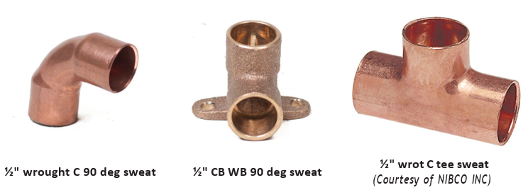
You may have noticed that pressure fitting has not been stated in the descriptions in Figure 55. This is because the smallest DWV fitting is 1[latex]\frac{1}{4}[/latex] inch, so the fitting could be assumed to be pressure. Of course, this must be clear to the person who is going to supply the material to you.
Threaded Fittings
Threaded fittings are used for joining steel pipe, including stainless steels and brass pipe. Typically, threaded joints are used in gas piping, hot water and steam heating systems, for compressed air, fire protection or in any system where threaded piping is acceptable.
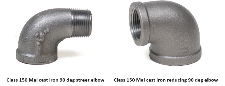
Figure 56 illustrates typical threaded fittings with their descriptions.
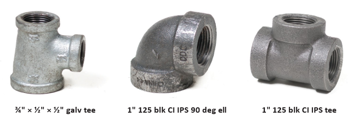
Threaded Fitting Classifications
Cast iron threaded fittings are available in classes 125 and 250. Malleable threaded fittings are available in classes 150 and 300, with black or galvanized finishes.
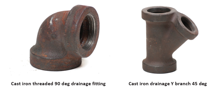
Cast Iron Drainage Fittings
Cast iron threaded drainage fittings (also known as Durham fittings) have an interior shoulder to create a smooth, continuous interior surface. Figure 58 illustrates cast iron drainage fittings. Cast iron drainage fittings are no longer used on new installations.
Flanged Fittings
Flanged fittings are another pipe joint method used where ease of assembly and disassembly of piping or system components is required. Flanged joints are assembled using flange gaskets and bolts. Flanges are made from various materials, including steel, cast iron, and brass.
Flange Fitting Classifications
Flanges are designated in several classes according to the material from which they are made. It is best to consult the job specification and/or manufacturer’s information to obtain the correct classification of the flange you require.
Flange Styles
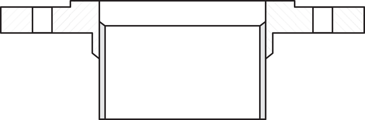
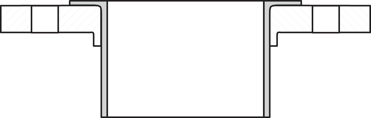
Flanges are available in different styles, some of which are:
- Weld-neck flange
- Slip-on flange
- Lap joint flange
- Threaded flange
- Socket flange
- Blind flange
Figures 59 to 63 illustrate these flange styles.


Flange Faces
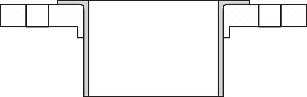
Flanges are manufactured with a variety of face types, some of which are:
- Flat face
- Raised face
- Ring joint face
- Lap joint face
Figures 64 to 67 illustrate these flange face types.

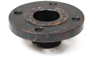

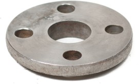
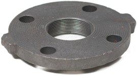
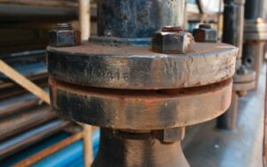
Flange faces may have smooth or serrated finishes (Figures 68 and 70).
Identify Flange Types
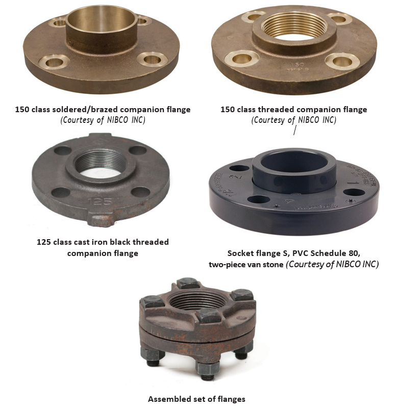
A companion flange is a pipe flange designed to receive a pipe length, and drilled so it may be bolted to another similar flange—or any flange that fits together in companion to another flange. The term is often referred to as a flange that is not part of a valve or piece of equipment.
The following are several examples of different types of manufacturers’ companion flanges.
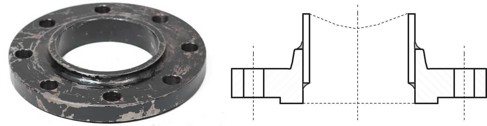
Slip-on Pipe Flanges
Slip-on pipe flanges actually slip over the pipe. These pipe flanges are typically machined with an inside diameter slightly larger than the outside diameter of the pipe. Slip-on pipe flanges are secured to the pipe with fillet welds at the top and bottom of the slip-on pipe flange.
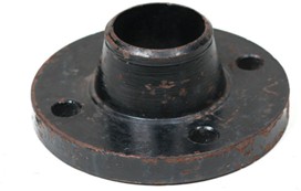
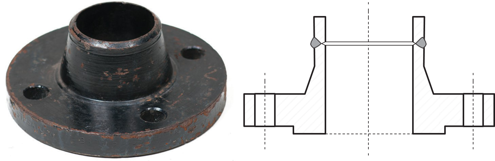
Weld-neck Pipe Flanges
Weld-neck pipe flanges attach by welding the neck of the flange to the pipe. This reduces the high concentration of stress at the base of the flange hub and transfers the stress from the flange to the pipe. This makes weld-neck pipe flanges suitable for high-pressure applications.
Weld-neck pipe flanges are machined so that their inside diameter matches the inside diameter of the pipe. Weld-neck pipe flanges have raised, flat or RTJ facing. Weld-neck pipe flanges under 400 pounds have a standard raised face height of [latex]\frac{1}{16}[/latex] in. For flanges of 400 pounds or more the standard is [latex]\frac{1}{4}[/latex] in.
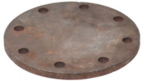
Blind Pipe Flanges
Blind pipe flanges are pipe flanges used to seal the end of a piping system or pressure vessel openings to prevent flow. Blind pipe flanges are commonly used for pressure testing the flow of liquid or gas through a pipe or vessel. Blind pipe flanges also allow easy access to the pipe in the event that work must be done inside the line.
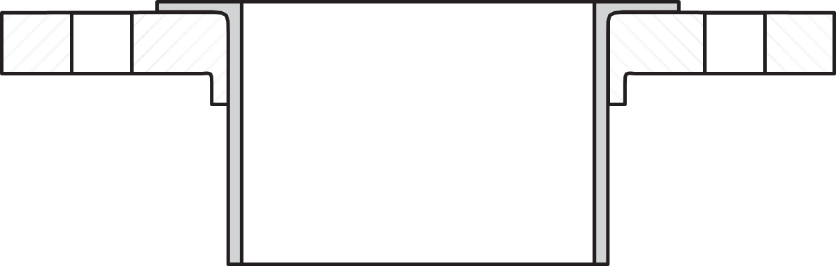
Lap Joint Pipe Flanges
Lap joint pipe flanges are usually used together with a matching stub end that fits inside the flange. The stub end is welded to the pipe, and the flange is left free to rotate around the stub end. The same arrangement is made on the pipe section that is to be joined together. The ability of the flanges to rotate means that the bolt holes on each flange can be easily aligned when bolting the pipe sections together. Lap joint pipe flanges are often used in systems where frequent dismantling is required.
Threaded Pipe Flanges
Threaded pipe flanges resemble slip-on pipe flanges except that the bore of the threaded pipe flange has tapered threads that enable the flange to be attached to a pipe that has external threads. This eliminates the need for welding. Threaded pipe flanges are generally used with small-diameter piping that operates under high pressure.
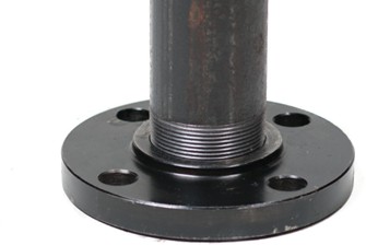
Socket Weld Flanges
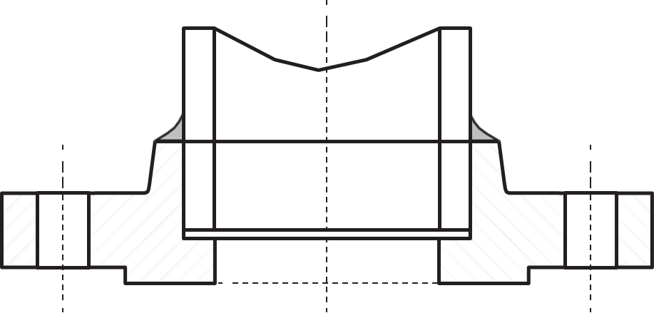
Socket weld pipe flanges have a recess on their inside surface that creates a smooth bore when the correct size of piping is inserted. This enables a smooth flow of fluid through the joint. The flange is attached to the pipe by a fillet weld around the top edge of the flange. Typical applications are in high-pressure, small-diameter piping systems.
Welded Fittings
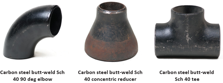
Welded fittings are used for joining steel pipe, and are available in elbows, tees, flanges, increasing and reducing types.
Figure 78 show various welded fittings. Refer to Level 1 B-5 Use Soldering and Brazing and Oxy-Fuel Cutting Equipment and D-1 Describe Piping and Tubing Materials for more information on pipe welding, fitting, and fabrication.
Socket Welded Fittings
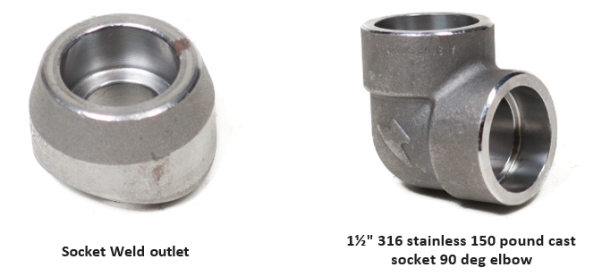
Socket welded fittings are typically used to connect smaller pipe diameters such as 2 inch and under. The socket weld connection is made by slipping the pipe into the socket of the fitting, then fillet welded.
Compression Fittings
Compression-type fittings similar to the one shown in Figure 80 can be used to join copper tubing, steel piping, PVC, polyethylene, and polybutylene.
Compression fittings consist of the following parts:
- Compression fitting body
- Compression ferrule
- Compression nut

The design of compression fittings can vary, but they all rely on the same principle: As a coupling nut is tightened onto the fitting, the ferrule is compressed against the tubing into a tapered seat.
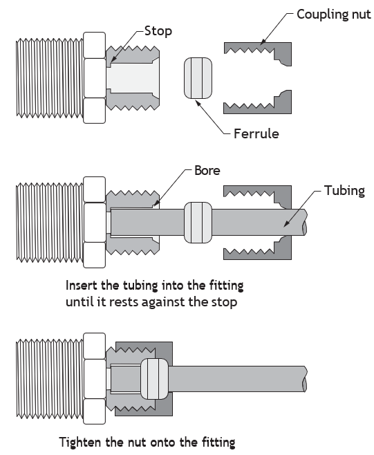
Figure 82 shows examples of compression fittings.

Insert Sleeves
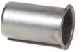
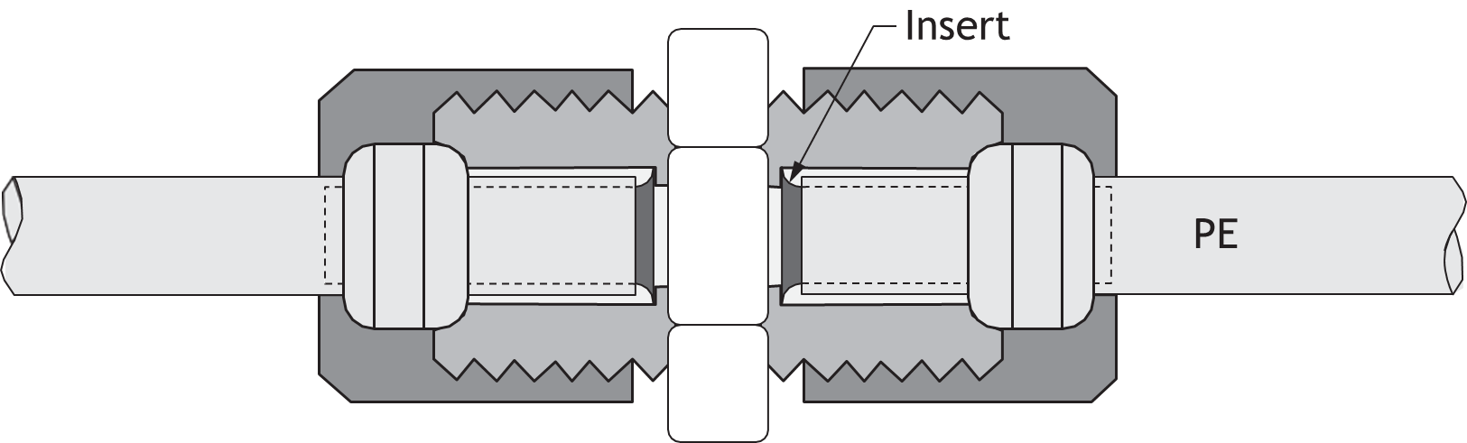
A plastic or metal insert sleeve is used with some types of plastic tubing compression fittings. The insert sleeve provides additional support to the walls of the tubing. Many manufacturers have designed compression fittings for use with specific types of tubing or pipe. When identifying compression fittings, it is important to include in your description the specific tubing type to which the fitting will be joined (e.g. PE, PB, PEX, etc.).
Always check the manufacturer’s information for specific requirements as to where and how the fitting is to be used. You must order the correct fitting to match the tubing or pipe, otherwise the warranty will not be valid. It is not a good idea to mix and match fittings and use them for applications for which they were not specifically designed.
The fitting shown in Figure 84 is a generic example of a plastic tubing compression coupling using an insert sleeve.
Flare Fittings
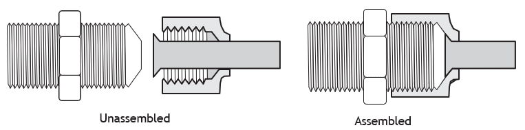
Flare fittings are a type of compression fitting generally used to join copper tubing, although they can also be used with other types of tube and piping systems. Flare nuts can be machined from brass stock or forged (cast brass).
Three types of flare fittings are available:
- SAE flare
- Inverted flare (discussed below)
- JIC flare
The SAE flare is the flare that is most commonly used by the plumbing trade for gas copper tubing systems. The angle of the SAE flare is 45 degrees.
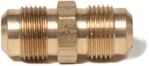
The JIC flare is suitable for hydraulic fittings and steel tubing. The angle of the JIC flare is 37 degrees.
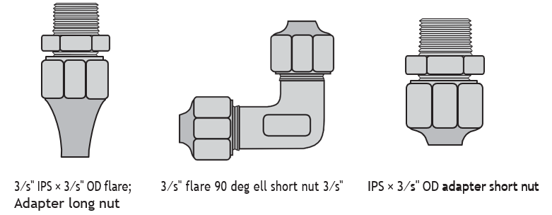
Figures 86 and 87 show examples of SAE flare fittings.
Flare Nuts
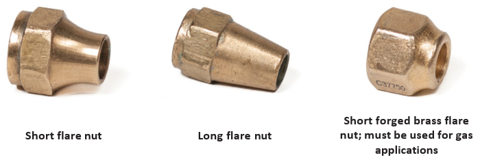
Machined brass long and short flare nuts are not to be used on gas systems, they must be forged as seen in Figure 88.
The following images show a series of flare nuts.
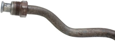
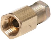
Inverted Flare
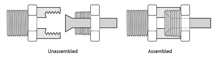
A flare nut fits over the flared end of a brake or fuel pipe at a union, used to clamp the tubing flare against another fitting. The inverted flare is usually used in the automotive industry for fuel lines and brake lines.
Figures 89 to 91 show various inverted flare fittings.
Quick-Connect Fittings
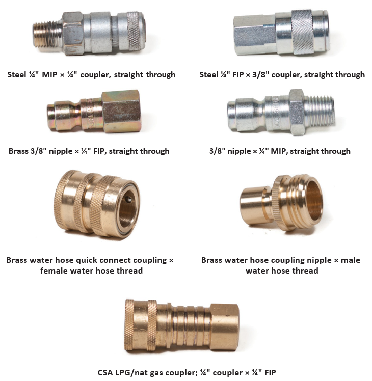
Quick-connect fittings, as the name suggests, are used to make quick connections, usually for pneumatic, hydraulic, and water hoses, and piping and equipment. They are made out of steel, stainless steel, brass, or plastic.
Figure 92 shows examples of quick connect fittings.
Insert Fittings for Polyethylene
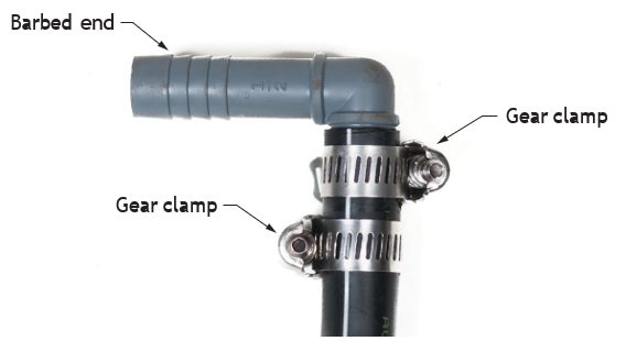
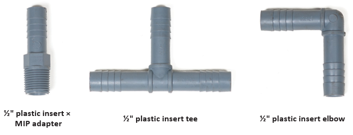
Insert fittings are another type of fitting used to join polyethylene tubing. Insert fittings may be made of brass, copper, galvanized iron, or plastic. Insert fittings have barbed ends that help to hold the fitting in place and seal the joint inside the tubing. A stainless steel gear clamp is used to squeeze the pipe onto the fitting.
An extra gear clamp is sometimes applied on the elbow when a little more insurance against leakage or pulling apart is desired. The gear clamps are installed in alternating directions to each other for a better seal (Figure 93).
There are different pressure designations of polyethylene tubing. It is important to identify exactly what type of tubing you are working with when ordering these fittings. Insert fittings used with gear clamps are designed to work with polyethylene of series 75, 100, 125, etc. They are not designed for series 160 golden-flow PE or PEX tube. Note: Insert fittings using gear clamps are not approved by the plumbing code for use in potable water systems.
PEX Fittings
PEX fittings are available in a variety of types to suit various types of installations. They can be made from metal or poly, and can use the push connection method.
Polybutylene (PB) plastic pipe is a grey-coloured, flexible pipe that was introduced in the 1980s and was installed in many residential buildings. The pipe has since been discontinued and PEX piping has taken its place. Polybutylene pipe is included here because you may have to repair existing systems.
The BC Plumbing Code (Part 7 of the BC Building Code) (Canadian Commission on Building and Fire Codes, 2022) only permits the use of series 160 PE (Polyethylene) for a water service pipe underground outside the building and underground inside the building. Series 160 PE is not to be used above ground inside the building. Series 160 PE uses compression fittings for joining.
PEX can be used for both hot- and cold-water piping. PEX can be installed outside below ground and inside the building above and below ground. However, crimp joints and expanding ring joint methods are not permitted underground. One word of caution: some manufacturers require that no PEX piping be used to connect to a hot water storage heater within 458 mm (18 in.) of storage heater piping connections.
PEX/aluminum/PEX is a composite pipe used in the hydronic heating industry. It is also approved for potable water. This pipe has been discontinued.
PEX Crimp Fittings
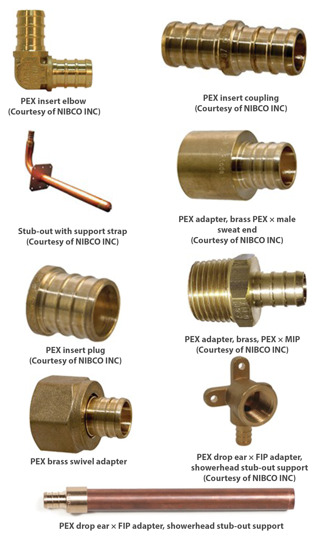
Crimp fittings are designed to join cross-linked polyethylene used in domestic water systems. The fittings were originally made of plastic (no longer approved), but they are now made from wrought copper or brass. Crimp fittings insert into the tubing. Note: Crimp fittings used for PEX are not to be used with gear clamps or polybutylene fittings. Look closely at the barbs on the insert fittings and compare them to the barbs on the crimp fittings—note the difference.
Crimp Rings
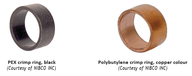
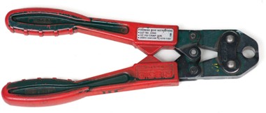
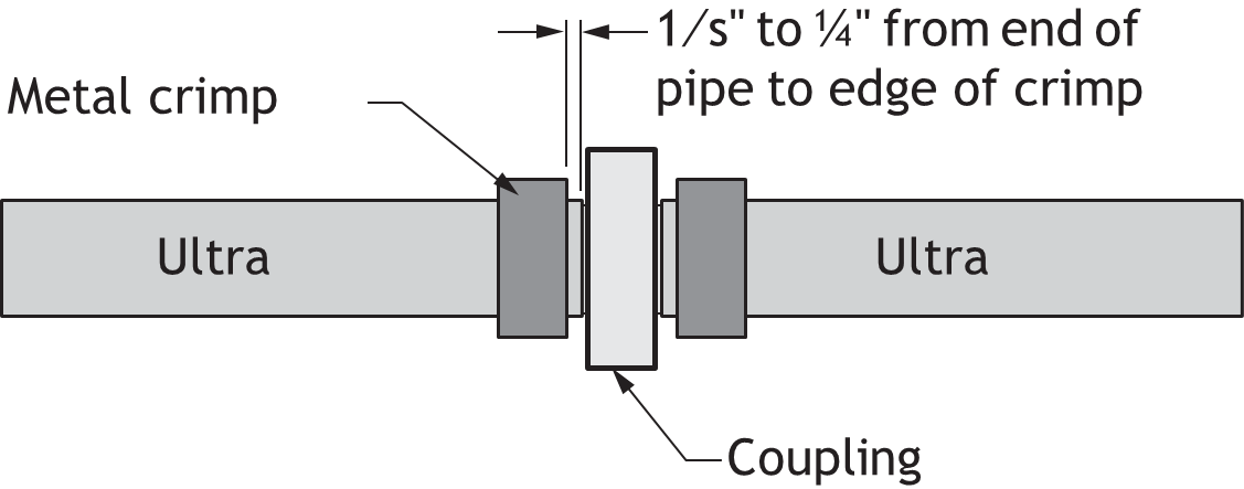
Crimp rings (Figure 96) slide over the tubing and positioned over the fitting. A special crimping tool (Figure 97) is used to squeeze the crimp ring onto the tube and fitting, creating a leak-tight joint. Figure 98 shows the correct placement of crimp rings before crimping.
Crimp Gauges
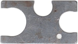
After installing a crimp fitting and crimp rings, use a Go/No-go gauge (Figure 99) to check the crimp for correct compression.
First, slide the Go side of the gauge over the crimped ring. If the crimp was made correctly, the gauge will pass over the ring with no problems.
Then turn the gauge over and try to pass the No-Go side of the gauge over the crimp ring. The crimp ring should be unable to enter the gauge at any point on the No-Go side of the gauge.
If the crimp ring fails either test, cut the PEX fitting out and replace it with a new crimp ring and fitting.
SDR Fittings
SDR stands for standard dimension ratio. It is an identification system that is used on plastic tubing. For example, you may read the number SDR 9 stamped on a PEX plastic tube. The number 9 is found by dividing the average outside diameter by the minimum wall thickness. Comparing two similar tubes from the same manufacturer, one with an SDR 11 rating and one with an SDR 9, typically the SDR 9 rating would have a higher pressure rating than the SDR 11 rating. The thicker the pipe wall, the lower the SDR number will be.
Transition from PEX to Polybutylene Piping
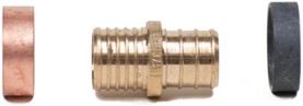
When transitioning from PEX tubing to polybutylene piping, you must use the correct transition coupling and crimp rings for each type of pipe.
Figure 100 shows a coupling used to connect PEX piping to PB piping. The left side is used for PB and the right side is for PEX. Notice that the PEX side has three rings and the PB side has four rings.
Oxygen Barrier
An oxygen barrier is a plastic layer on the outside of PEX tubing in hot water heating systems. The oxygen barrier prevents oxygen from permeating through the tube into the water. Water containing oxygen can damage the heating system by corroding or oxidizing the metal components of the system.
ProPEX (Wirsbo) PEX Fittings
ProPEX (formally called quick and easy) rings are manufactured from PEX-A material, and are required to make a proper ProPEX connection.
- Wirsbo = brand (older name people still use) – now part of Uponor
- ProPEX = connection method (expansion system)
ProPEX rings and pipe come in red, blue and white. This colour-coding helps identify the piping system as conveying hot or cold, and reduces the chance of unintentionally cross-connecting the hot and cold water supplies.
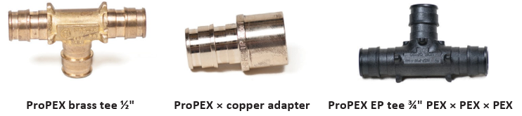
Figure 101 shows examples of expansion ring fittings.
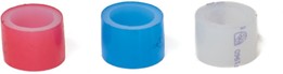
ProPEX® fittings are made from brass or engineered plastic (EP).
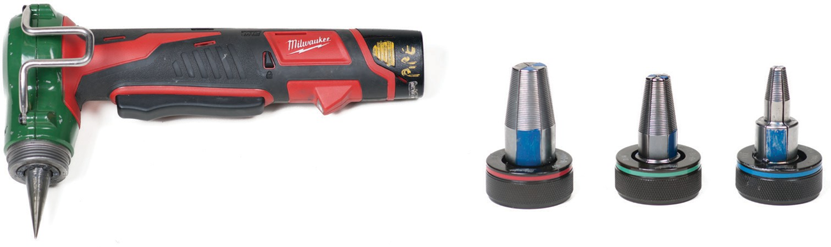
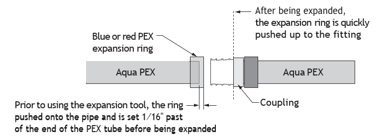
These rings are not crimped using a crimping tool. After the ring has been positioned on the pipe, an expanding tool (Figure 103) is used to expand the pipe end and the ring at the same time.
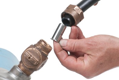
The expanded pipe and ring are then quickly slid over the fitting up to the stop lugs on the fitting (Figure 104). After a very short time the pipe and ring contract and compress onto the fitting. When the procedure is completed according to the manufacturer’s directions, the joint is tight and leak- proof.
Compression Fittings and PE or PEX Connections
A stainless steel, plastic or brass stiffener/sleeve must be used inside the end of the PE or PEX tubing to prevent the plastic pipe from collapsing inward when the compression nut is tightened. If the stiffener is not used, the connection may fail. Check the manufacturer’s directions for accurate assembly of these compression fittings and tubing.
PEX/AL/PEX Fittings
PEX/AL/PEX [Cross-link Polyethylene (PEX)/Aluminum (AL)/Cross-link Polyethylene (PEX)] has been discontinued, but you may find this tube and fittings on the job.
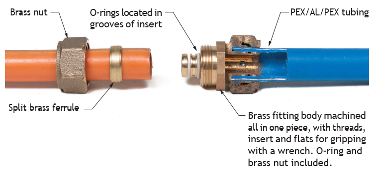
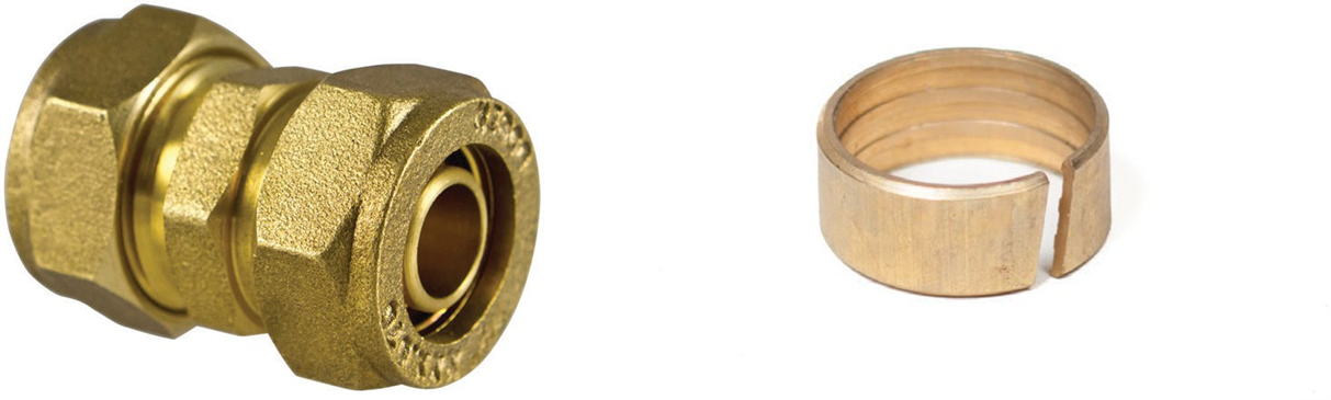
Fittings used to join PEX/AL/PEX tubing are manufactured specifically for this tubing. The fittings are a type of compression fitting that has a built-in insert complete with two O-rings that slip inside the tube. A nut is first slipped onto the tubing and a split brass ferrule is then slipped over the end of the tube. The fitting and tube are then pushed together until the tube bottoms out in the socket of the fitting. When the nut is tightened with a wrench, the ferrule is compressed against the tube, completing a tight joint.
Push Fittings
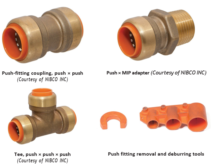
The push-fitting system is completed without any soldering, crimping or joining materials. These fittings can be used to join PEX, copper, CPVC, or CTS pipe. Refer to the manufacturer’s instructions.
Push fittings are available in a variety of types, including adapters, caps, couplings, elbows, and tees.
Figure 108 shows examples of push fittings.
The press-fit joint fitting is a quick seal that is reliable, permanent and watertight. The press system joins seamless copper water tube or PEX in residential and commercial potable, hot, chilled and process water applications for plumbing and HVAC systems.
The term “press-fit” refers to a generic connection method. A number of companies manufacture tools and fittings for these types of systems. All press-fit fittings can be used with standard pipe or tubing that they were made for, but check with manufacturers’ literature to be sure that the pressing tools can be used with intended fittings before making any connections.
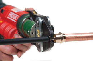
Press fittings are available in a broad range, including adapters, caps, couplings, elbows, flanges, manifolds, tees, and unions. Figure 110 shows examples of press fittings.
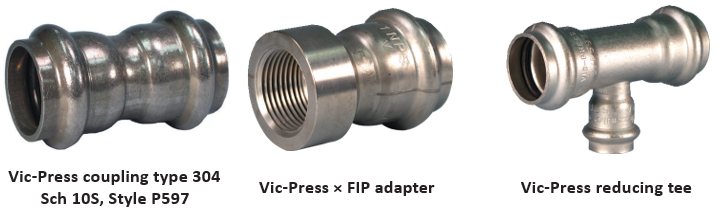
Vic-Press
Vic-Press is a patented system manufactured by the Victaulic Co. that uses stainless press fittings and pipe for sprinkler systems. Figure 111 shows various types of Vic-Press fittings.
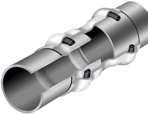
Vic-Press couplings have internal rubber O-rings to create a seal as seen in Figure 112.
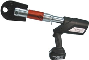
The Vic-Press® tool compresses the fitting to create a rigid mechanical connection as seen in Figure 113.
CPVC Fire Protection
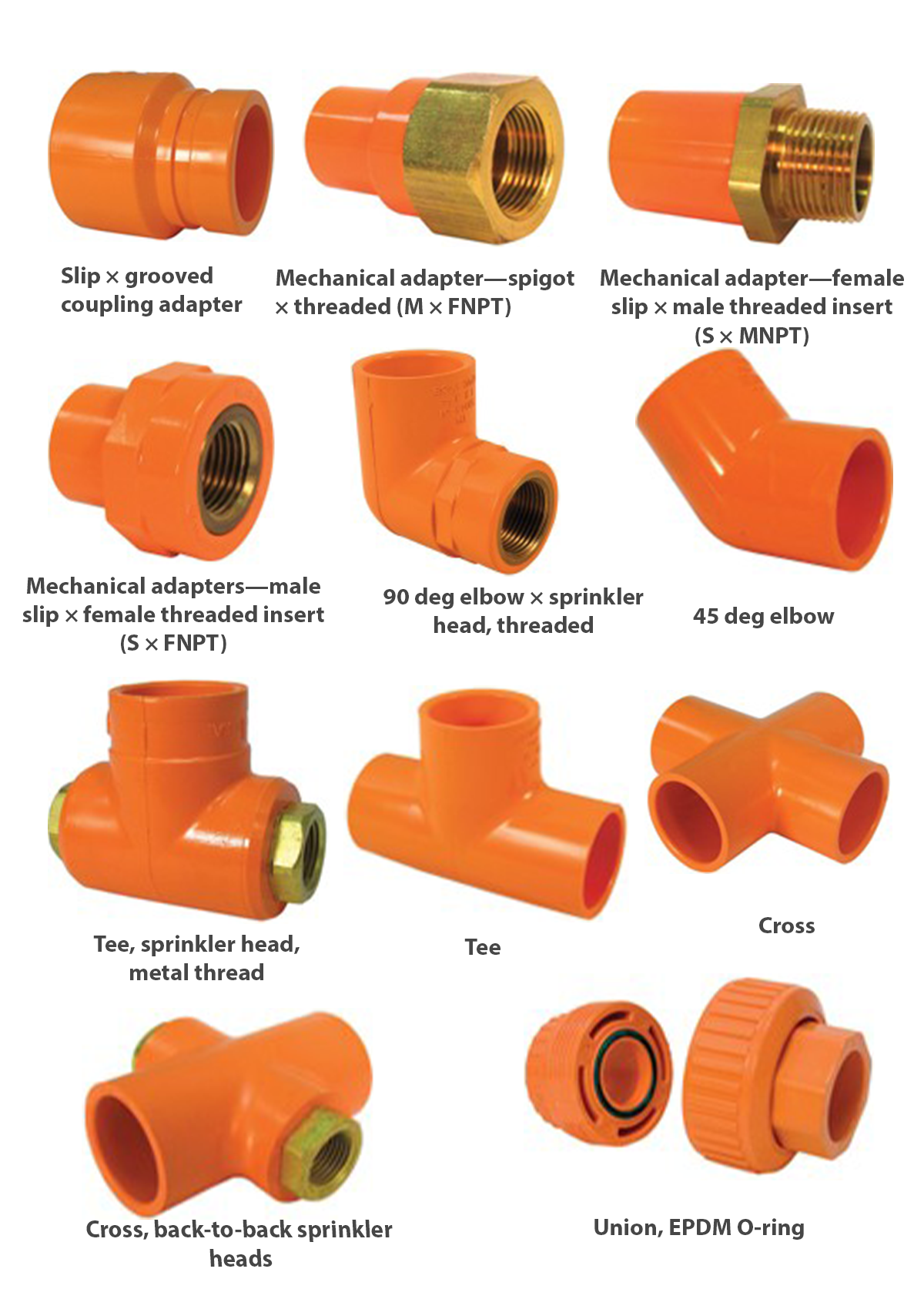
Injection-moulded CPVC thermoplastic fittings are designed for use in residential and commercial fire protection and fire sprinkler systems. Fittings include adapters, bushings, caps, couplings, crosses, elbows, flanges, tees, and unions.
Figure 114 shows examples of CPVC thermoplastic fittings.
PVC Schedule 80 Fittings
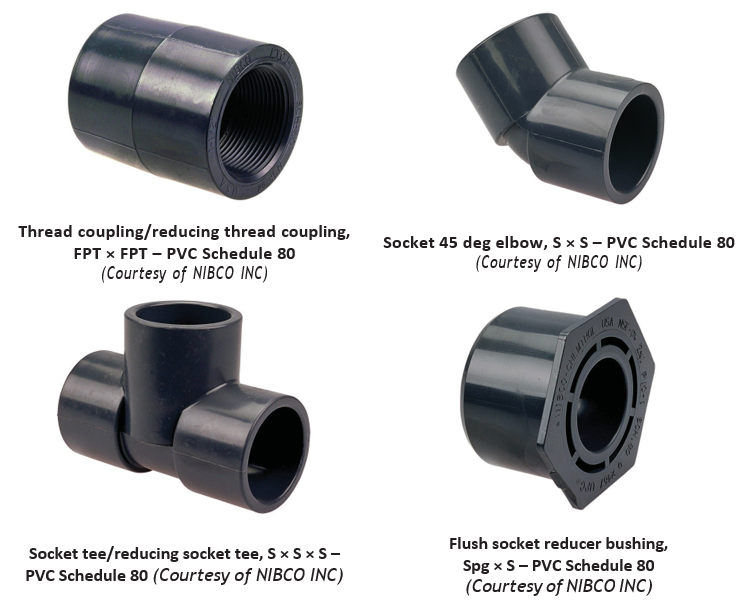
Polyvinyl chloride (PVC) Schedule 80 fittings are designed for use with chemical processing, industrial plating, chilled water distribution, deionized water lines, chemical drainage and waste water treatment systems.
Figure 115 shows various types of PVC Schedule 80 fittings.
PVC Schedule 40 Fittings
PVC Schedule 40 fittings are similar to Schedule 80 fittings; however, they are not designed to withstand higher pressures.
Mechanical Joint Fittings
The term mechanical joint fittings refers to a variety of fittings that use specially designed clamps and elastomeric gaskets to connect the pipe and fittings. Many of these fittings are described by the manufacturer’s name, such as Victaulic or Gruvlok. A mechanical joint clamp used for joining cast iron no-hub DWV pipe and fittings is simply referred to as an MJ clamp.
Elastomeric refers to a flexible synthetic rubber-like compound (neoprene) designed for specific uses. Some elastomeric compounds, for example, must be able to resist different chemicals, temperatures and pressures. Manufacturers supply elastomeric gaskets for many different applications.
Grooved Fittings
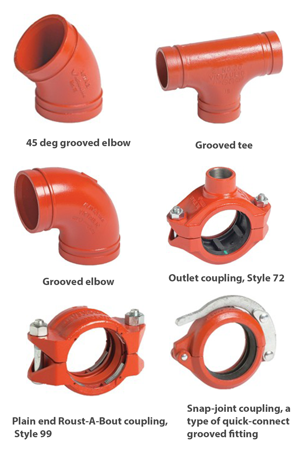
Victaulic and Gruvlok fittings are used to join steel pipe and tubing, copper tubing, or piping materials that are suitable for grooving. The term grooving refers to a process of rolling or cutting a groove into the end of the pipe. The groove provides a channel into which the clamp body fits, as shown in the joint cross-section in Figure 116. The clamp is held together with bolts and the elastomeric gasket.
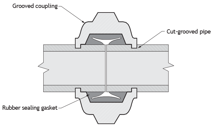
When describing these types of fittings, you are often required to include the name of the manufacturer and specify the gasket required to suit the pressures, temperatures and fluid that will be transported.
Victaulic’s Zero-Flex coupling (Figure 117) adjusts so that it can be clamped to a pipe with standard pipe tolerances, providing resistance to flexing and twisting.
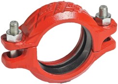
Figure 118 shows various types of grooved fittings. The plain end Roust-A-Bout coupling, also from Victaulic, features gripping teeth that help form a strong joint between plain and bevelled ends (including Schedule 80 carbon steel pipe). However, it cannot be used on plastic pipe, pipe with brittle linings, cast or ductile iron pipe, or any pipe with a surface hardness greater than 150 Brinell.
Mechanical Joint Couplings for Cast Iron Drainage
A mechanical joint (MJ) coupling is used to join no-hub cast iron DWV piping and fittings. The coupling is a neoprene sleeve inside a stainless steel sleeve with attached gear clamps. Mechanical joints have replaced the bell and spigot (lead and oakum) joint.
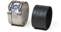
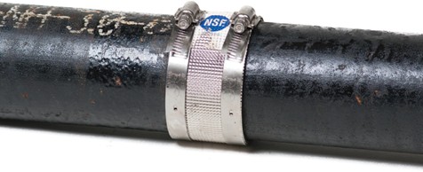
MJ clamps can be made entirely of elastomeric compounds with individual gear clamps and no stainless steel sleeve. These clamps are used as transition couplings (adapters) from one type of piping material to another, and can be purchased as straight or reducing couplings. They are popular for renovations.
Bushings can be purchased that will allow a standard size clamp to be used to join pipes of the same size but with different OD. The bushing fits inside the clamp to adapt to the OD of the smaller pipe (Figure 120).
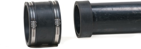
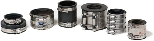
MJ couplings are quite flexible—they make leak-proof seals on virtually any pipe material: plastic, cast iron, asbestos cement, clay, concrete, steel, copper, and ductile iron. All couplings are clearly marked with part number, size, and pipe materials that the coupling will connect.
Some examples of trade names for these clamps are Zip, Fernco, Mission Clay, and Rollee. When you describe these clamps, you should include the trade name in the description.
Push-on Fittings
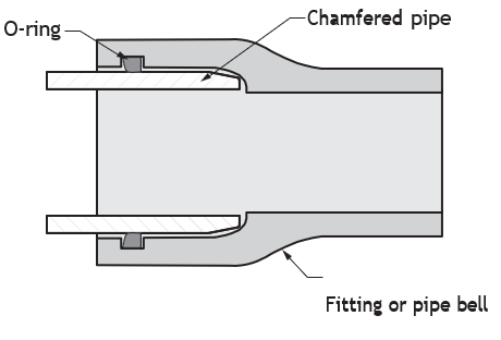
A push-on joint is a type of fitting that resembles a bell and spigot joint. These joints are used extensively for water mains, sanitary and storm sewers, and municipal services.
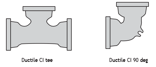
Push-on fittings are available in a variety of materials for different piping materials, including PVC and ductile cast iron. This method of joining pipe uses a type of ring gasket, which is placed in a groove in the hub of the fitting. The gaskets may be designed for use with only the fittings of a specific manufacturer. You must specify the manufacturer of the fittings to ensure you receive the right gaskets.
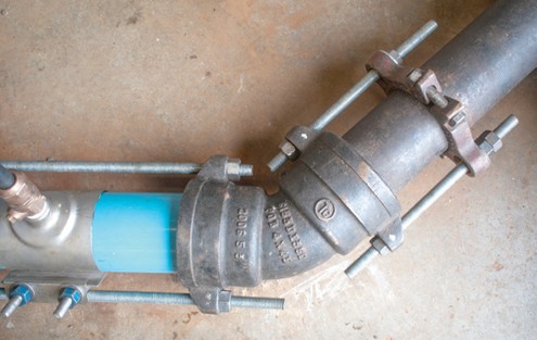
Push-on fittings must be restrained when they are pressurized in use. Fitting restraint is accomplished by a system of rodding, thrust blocks, and clamping devices.
 Self-Test D-3.1 Describe Fittings Used in the Pipe Trades
Complete Self-Test 3.1 and check your answers.
If you are using a printed copy, please find Self-Test D-3.1 and Answer Key in the Appendix at the end. If you prefer, you can scan the QR code with your digital device to go directly to the interactive Self-Test.

References
BC Industry Training Authority. (2019). Piping trades apprenticeship program: Use Tools and Equipment—Level 1 harmonized [Binder]. Crown Publications, Queen’s Printer for British Columbia. https://www.crownpub.bc.ca/Product/Details/7960000261_S
- Plumber: Competency D-5 Install Fittings
- Steamfitter: Competency D-2 Install Fittings
- Sprinkler Fitter: Competency D-5 Install Fittings
Canadian Commission on Building and Fire Codes. (2022). National plumbing code of Canada: 2020. National Research Council Canada. https://nrc-publications.canada.ca/eng/view/object/?id=6e7cabf5-d83e-4efd-9a1c-6515fc7cdc71
CSA Group. (2025). CSA B149.1:25—Natural gas and propane installation code. https://www.csagroup.org/store/product/CSA_B149.1%3A25_OT/
Province of British Columbia. (2006). British Columbia Building Code 2006, Part 7.7.4. Queen’s Printer. https://free.bcpublications.ca/civix/document/id/public/bcbc2006/building_b_p7_7.4
Smith, L. (2013). IPT’s pipe trades handbook (10th ed.). IPT Publishing and Training Ltd.
Victaulic. (n.d.). Victaulic: Mechanical pipe joining solutions. https://www.victaulic.com/
Victaulic. (n.d.). Style 07 zero-flex rigid coupling. Victaulic. https://www.victaulic.com/products/style-07-zero-flex-rigid-coupling/
Media Attributions
All figures are sourced from Industry Training Authority (2019) and/or Camosun College (2019) and are used under the Creative Commons Attribution 4.0 (CC BY 4.0) licence unless otherwise noted. Images copyrighted by the BC Industry Training Authority are licensed under a Creative Commons Attribution-NonCommercial-ShareAlike 4.0 (CC BY-NC-SA 4.0) licence.
- The following images are courtesy of NIBCO INC. and are used with permission:
- Figure 18 Double sanitary fittings
- Figure 19 ABS tee wye combination, long radius
- Figure 21 ABS DWV left and right side inlet hubs
- Figure 27 Copper tube couplings
- Figure 33 Various types of union
- Figure 37 Adapter fittings
- Figure 39 Various types of plugs and caps
- Figure 40 Various types of cleanouts
- Figure 50 ABS traps
- Figure 55 Soldered fittings
- Figure 71 Flange types
- Figure 95 PEX crimp fittings
- Figure 96 Crimp rings
- Figure 107 PEX compression coupling, nuts and brass ferrule
- Figure 108 Push fittings
- Figure 114 CPVC Fire protection fittings
- Figure 115 PVC Schedule 80 fittings
- Figure 40 [Various types of cleanouts] Ongrade adjustable cleanout is courtesy of Watts and is used with permission.
A list of materials needed for a job. (Section D-3.1)
Fittings used to carry drainage, waste, and vent fluids by gravity. (Section D-3.1)
Fittings designed to carry fluids under pressure. (Section D-3.1)
The curved part of a fitting that determines how sharply it changes direction. (Section D-3.1)
The inside curved portion of a fitting where flow changes direction. (Section D-3.1)
An imaginary line that runs through the centre of a pipe or fitting. (Section D-3.1)
The end of a fitting that receives another pipe or fitting. (Section D-3.1)
The end of a pipe or fitting that fits into a hub end. (Section D-3.1)
The flat surface of a flange where it meets another flange or gasket to form a seal. (Section D-3.1)
A smooth, flexible copper fitting made by shaping metal rather than casting, commonly used in pressure piping systems. (Section D-3.1)
A metal material used to make fittings, with a rougher surface and lower flexibility than copper. (Section D-3.1)
The ability of a metal to be shaped or bent without breaking. (Section D-1.6)
Joining metal using heat and a filler metal at high temperatures. (Section D-1.6)
A copper fitting used to connect soldered copper pipe to a female threaded connection in pressure systems. (Section D-3.1)
A fitting used to change the direction of a pipe. (Section D-3.1)
A fitting with a gradual curve that allows smoother flow and reduces pressure loss. (Section D-3.1)
A fitting with a tighter curve that changes direction quickly but may cause more flow resistance. (Section D-3.1)
A common fitting bend used to change direction, typically referring to a standard radius elbow. (Section D-3.1)
A fitting that changes direction by 180 degrees. (Section D-3.1)
An elbow with male threads on one end and female threads on the other. (Section D-3.1)
A threaded pipe connection with external threads that screws into a female threaded fitting. (Section D-3.1)
A threaded pipe connection with internal threads that receives a male threaded pipe or fitting. (Section D-3.1)
An elbow that changes both the direction and size of a pipe. (Section D-3.1)
A pipe fitting used to change direction, often used instead of the term elbow in DWV systems. (Section D-3.1)
An elbow with mounting tabs used to secure piping to a surface. (Section D-3.1)
A fitting that connects three pipes at a 90-degree angle, typically used in pressure piping systems. (Section D-3.1)
A fitting used in drainage systems to connect pipes at a 90-degree angle, designed with a curved shape to guide flow smoothly. (Section D-3.1)
A fitting used in drainage systems to connect four pipes at 90-degree angles, designed to guide flow smoothly and reduce blockages. (Section D-3.1)
A fitting that connects four pipes with angled branches. (Section D-3.1)
A fitting that combines a tee and a wye, with a longer-radius curve to direct flow more smoothly than a standard sanitary tee. (Section D-3.1)
A fitting used to connect pipes of different sizes. (Section D-3.1)
A fitting with an extra connection on the side. (Section D-3.1)
A threaded opening in a fitting used to connect to another pipe. (Section D-3.1)
A side opening on a fitting that is internally threaded to allow connection to another pipe or fitting. (Section D-3.1)
A fitting used to connect two pieces of pipe or tubing together in a straight line. (Section D-1.6)
A coupling without an internal stop that allows pipe to slide through. (Section D-3.1)
A material used during welding to protect the metal from air and impurities. (Section D-1.2; Section D-1.6)
A fitting that allows pipes or equipment to be easily connected and disconnected without cutting or rotating the pipe. (Section D-3.1)
A type of union that forms a tight seal using smooth, tapered metal surfaces, allowing pipes to be connected and disconnected without a gasket. (Section D-3.1)
A union that uses a washer to create a seal. (Section D-3.1)
(sometimes called transition fittings); A fitting used to connect pipes with different connection types. (Section D-3.1)
A fitting used to reduce the size of a pipe opening, usually with threaded ends. (Section D-3.1)
An MJ cast iron fitting that changes a pipe size. (Section D-3.1)
A fitting used to close the end of a pipe with internal threads. (Section D-3.1)
A fitting with external threads used to seal the end of a pipe. (Section D-3.1)
An access point in a pipe system used to remove blockages. (Section D-3.1)
The straight-through portion of a fitting. (Section D-3.1)
The pipe that connects off the main run of a fitting. (Section D-3.1)
A fitting with an additional opening on the side that allows another pipe to connect to the main fitting. (Section D-3.1)
A side opening on a fitting that has internal threads to allow connection to another pipe or fitting. (Section D-3.1)
A process where threads are cut into a hole so a pipe or fitting can be screwed into it. (Section D-3.1)
A fitting used in drainage systems to connect four pipes at 90-degree angles, allowing flow in multiple directions. (Section D-3.1)
A plastic DWV fitting that connects four pipes using two angled (typically 45°) branches for smoother flow and reduced blockages. (Section D-3.1)
A tee fitting where flow enters through the branch and splits in opposite directions through the run, often causing turbulence and pressure loss. (Section D-3.1)
A curved section of pipe that holds a small amount of water to prevent sewer gases from entering a building. (Section D-3.1)
A short length of pipe with threads on one or both ends used to connect fittings or extend piping. (Section D-3.1)
A very short threaded pipe with threads running nearly the entire length, used to connect two fittings closely together. (Section D-3.1)
A short pipe with a small unthreaded section (shoulder) between the threaded ends, allowing better wrench grip during installation. (Section D-3.1)
A longer length of threaded pipe used to connect fittings that are spaced farther apart. (Section D-3.1)
A fitting joined by heating and melting solder to seal and connect the pipe. (Section D-3.1)
A fitting joined by heating and melting a filler metal to create a strong, high-temperature joint. (Section D-3.1)
A fitting with internal or external threads that is screwed onto a pipe to form a connection. (Section D-3.1)
A threaded cast iron fitting used in drainage systems that can be taken apart and reused. (Section D-3.1)
A threaded cast iron fitting used in drainage systems that can be taken apart and reused. (Section D-3.1)
A flange used to connect a pipe to equipment or another flanged component, often matching the bolt pattern of the mating flange. (Section D-3.1)
A flange that slides over the pipe and is then welded in place to secure it. (Section D-3.1)
A flange with a long neck that is welded to the pipe, providing strong support and smooth flow. (Section D-3.1)
A solid flange used to close off the end of a pipe or opening. (Section D-3.1)
A flange used with a stub end that can rotate, making it easier to align bolt holes during installation. (Section D-3.1)
A flange with internal threads that screws onto a pipe, eliminating the need for welding. (Section D-3.1)
A flange with a recessed socket that the pipe fits into before being welded, providing a strong and aligned connection. (Section D-3.1)
A fitting that is permanently joined to a pipe by melting and fusing the metal together to create a strong, leak-proof connection. (Section D-3.1)
A fitting with a recessed socket that a pipe is inserted into and then welded around the joint to create a strong, leak-proof connection. (Section D-3.1)
A fitting that uses a nut and compression ring (ferrule) to squeeze and seal a pipe without the need for heat or threading. (Section D-3.1)
A small metal ring that fits around a pipe or tube to help create a tight seal and hold the connection securely when tightened. (Section D-1.6)
A small tube, made out of plastic or metal, placed inside a pipe to support it and help maintain its shape when making a connection. (Section D-3.1)
A fitting that seals by pressing a flared (widened) pipe end against a matching surface to create a tight connection. (Section D-3.1)
A type of flare fitting with a 45-degree angle, commonly used in automotive and refrigeration systems. (Section D-3.1)
A type of flare fitting with a 37-degree angle, commonly used in hydraulic systems. (Section D-3.1)
Nuts used with flare fittings that tighten onto the fitting to press the flared pipe end and create a tight seal. (Section D-3.1)
A type of flare fitting where the flared end of the pipe is folded inward, providing a strong, leak-resistant connection commonly used in automotive and refrigeration systems. (Section D-3.1)
A fitting that allows pipes or tubing to be connected and disconnected quickly without the use of tools. (Section D-3.1)
A fitting used to join polyethylene (PE) tubing by inserting into the tubing and securing it with clamps or compression rings to create a tight seal. (Section D-3.1)
A metal band clamp with a screw mechanism that tightens around a pipe or hose to hold it securely in place. (Section D-3.1)
A fitting used to connect PEX (cross-linked polyethylene) tubing, typically secured with a crimp ring, clamp, or expansion method to create a watertight seal. (Section D-3.1)
A flexible plastic pipe once used for water supply systems, known for being easy to install but no longer commonly used due to failure issues over time. (Section D-3.1)
A fitting used with PEX tubing that is secured using a crimp ring to form a tight, leak-resistant connection. (Section D-3.1)
A metal ring that is compressed around PEX tubing to hold it tightly onto a fitting and create a watertight seal. (Section D-3.1)
A tool used to check if a crimp connection is properly sized by confirming whether it passes or fails specific measurement limits. (Section D-3.1)
A number that compares a pipe’s outside diameter to its wall thickness to show how strong it is and how much pressure it can handle. (Section D-1.1)
A layer in some piping (such as PEX) that prevents oxygen from passing through the pipe wall and entering the system, helping to reduce corrosion. (Section D-3.1)
A PEX connection system that uses expansion fittings and rings to create a tight seal as the tubing shrinks back to its original size. (Section D-3.1)
A type of PEX tubing made using the peroxide (Engel) method, known for being flexible and able to be repaired with heat. (Section D-1.2)
A multilayer pipe made of PEX with a thin aluminum layer in the middle, providing added strength, shape retention, and resistance to oxygen entering the system. (Section D-3.1)
A connection system that allows pipes or tubing to be joined by pushing them into a fitting, where internal seals and gripping rings create a secure, leak-resistant connection without tools. (Section D-3.1)
A method of joining pipes using a special fitting and tool that presses the connection together to form a tight seal. (Section D-1.6)
A patented press-connect piping system, manufactured by the Victaulic Co., that uses special fittings and a pressing tool to create a secure, leak-resistant connection without welding or threading. (Section D-3.1)
Fittings made by injecting molten CPVC plastic into a mould to form durable shapes used in piping systems, especially for hot and cold water applications. (Section D-3.1)
Strong plastic fittings with thicker walls than standard PVC, designed to handle higher pressure in piping systems. (Section D-3.1)
Standard plastic fittings with moderate wall thickness, commonly used for drainage, waste, vent, and some low-pressure piping systems. (Section D-3.1)
A fitting that connects pipes using bolts, gaskets, or clamps to create a tight seal without welding or threading. (Section D-3.1)
A clamp used with mechanical joint fittings to compress a gasket and secure the pipe connection, creating a tight seal. (Section D-3.1)
A material that is flexible and rubber-like, able to stretch and return to its original shape. (Section D-3.1)
The process of cutting or forming a groove near the end of a pipe so it can be joined using a grooved coupling or fitting. (Section D-3.1)
A rigid grooved coupling designed to join pipes with no movement at the joint, providing strong support and maintaining alignment. (Section D-3.1)
A pipe coupling that uses bolts, a gland, and an elastomeric gasket to compress and seal the connection without welding or threading. (Section D-3.1)
A pipe connection where the plain end (spigot) is inserted into the enlarged end (bell), then sealed with oakum and molten lead to create a watertight joint. (Section D-3.1)
A pipe connection where the spigot end is pushed into a bell with a rubber gasket to create a watertight seal without threading or welding. (Section D-3.1)