D-2.1 Describe Basic Valve Types
Valves are essential components in piping systems, used to control, direct, and regulate the flow of fluids. To work safely and effectively in the piping trades, it is important to understand the basic terminology used to describe valves, their parts, and how they operate. The following section introduces key valve terms and concepts that you will encounter on the job and in technical documentation.
Valve Terminology
It is important to be able to define basic valve terminology. You should be familiar with the following terms:
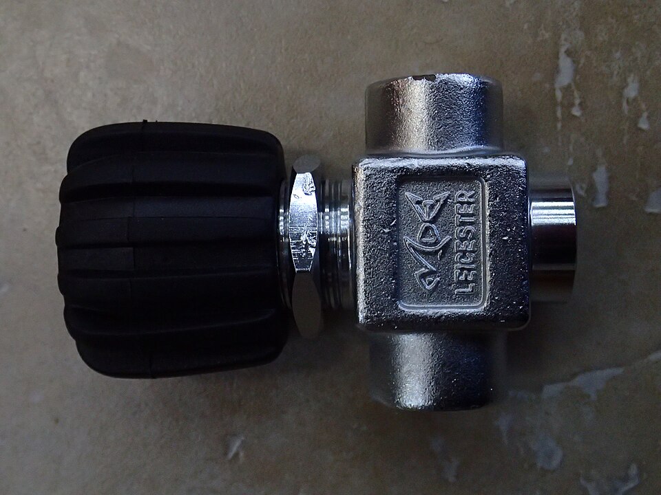
air valve: A valve used to control the flow of air.
backpressure: The pressure exerted on the downstream side of a valve seat.
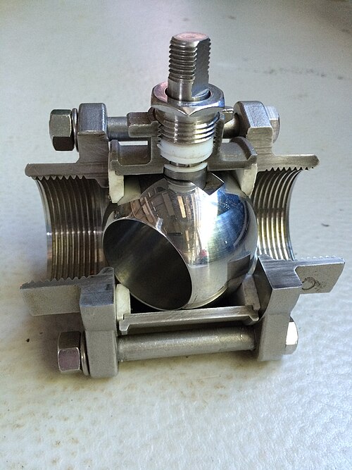
ball valve: A quarter-turn valve with a ball-shaped closing element held between two seats.
backwater valve: A check valve designed for use in a sanitary drainage system.
bellows: A sealing device that prevents line media from leaking between the stem and the body.
bidirectional valve: A valve that moves or operates in two opposite directions.
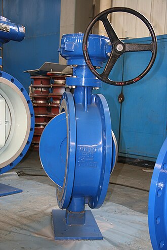
butterfly valve: A quarter-turn valve that has a circular disk as its closing element.
bypass valve: A small-bore valve fitted in parallel with a larger main valve.
cavitation: The noise and damage caused when high-velocity turbulent flow and low pressure occur in a valve forming gas bubbles that collapse rapidly; the gas bubble rapidly turns back into water when the velocity drops and the pressure increases. This results in deterioration of internal valve parts and premature failure.
check valve: A valve designed to allow fluid to flow in one direction only and prevent reverse flow. The valve closes to prevent backflow.
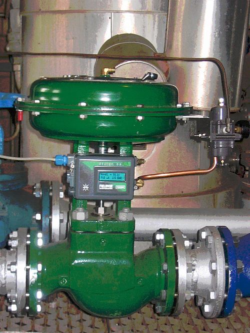
control valve: A valve that regulates the flow or pressure of a fluid. Control valves respond to signals generated by independent devices such as flow meters, temperature gauges, etc. Control valves are typically fitted with actuators and positioners.
cryogenic valve: A valve designed for use at temperatures below –40°C (–40°F).
diaphragm valve: A bidirectional valve operated by applying an external force to a flexible element, or diaphragm (typically an elastomer).
diverter valve: A valve that changes the direction of the flow of medium to two or more outlets/ directions.

double block and bleed: A valve configuration in which positive shut-off is achieved at both the inlet and outlet sides, with a pressure bleed between them.
elastomer: Any material, such as natural or synthetic rubber, that is able to resume its original shape when a deforming force is removed.
galling: A severe form of metal wear caused when sliding surfaces make contact, tearing areas of the metal surface.
lantern ring: A metal ring in a valve that provides for uniform distribution of stem packing pressure over the packing.
positioner: A device used to ensure that the valve is at the correct position of opening as the control signal indicates.
quarter-turn valve: A valve in which the handle and stem move from fully closed to fully open in one-quarter of a 360° turn (90°).
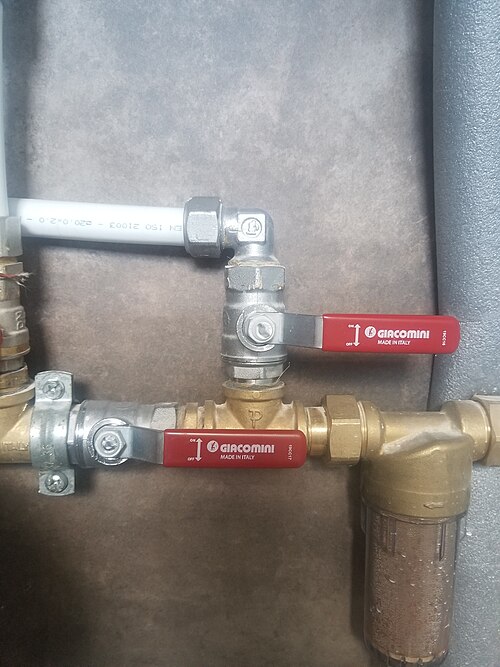
resilient seat: A valve disk or seat that is soft-seated rather than a metal-to-metal hard seat. An example is a Teflon seat.
stuffing box: An enclosure containing packing to prevent leakage around a moving machine part, such as a valve stem.
trunnion: A valve component such a pin or pivot on which something can be rotated, such in a trunnion ball valve, which has additional mechanical anchoring of the ball at the top and the bottom, suitable for larger and higher pressure valves.
valve actuator: A device used to open, close, or control a valve, such as manual handles and electrical, hydraulic, and pneumatic actuators.
valve chatter: The noise created when the water flow causes loose valve components to rattle or chatter in rapid succession.
valve packing: A sealing material, usually graphite, used to seal around a valve stem to prevent leakage of system fluids.
valve stem: The part of a valve that connects the handle or actuator to the internal closing part (such as a disk or gate) and moves to open or close the valve.
wire drawing: The visual effect of erosion of a valve seat or disk. Wire drawing occurs when a valve is not closed perfectly tight.
Valve Materials
The materials used to construct a valve play an important role in its ability to operate in the working environment to which it will be subjected. It may be unsafe to use materials for services beyond their recommended maximum limits.
Valve materials are selected by the following considerations:
- Pressure limitations
- Temperature limitations
- Structural limitations
Valve materials commonly used in industry include the following:
- Bronze
- Iron
- Malleable iron
- Ductile iron
- Steel
- Stainless steel
- Titanium
- Plastics
- Composites
Valve Purpose
The main purpose of a valve is often to turn on (start) or shut off (stop) the flow in a piping system. However, valves can serve many purposes, such as:
- Limiting pressure
- Regulating pressure
- Controlling flow rate
- Turning flow off and on
- Mixing water of different temperatures
- Limiting maximum temperature
- Preventing reverse direction flow
- Balancing flow across different circuits
Valve Classification
Valves can be classified into two general categories based on the motion of the valve stem/operator:
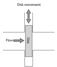
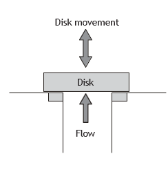
- Linear movement valves: The stem moves in a straight line. These include gate valves, globe valves, diaphragm valves and pinch valves.
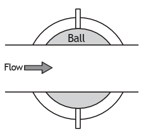
- Rotary movement valves: The stem rotates around an axis at right angles to the direction of flow. These include ball valves and butterfly valves.
|
Valve Movement |
Linear Motion |
Rotary Motion |
||
|
Operating motion of the closing device |
In a straight line |
Rotating about an axis at right angles to the direction of flow |
||
|
Direction of flow in the seating area |
At right angles to the operating motion |
Longitudinal to the operating motion |
Through the disk |
Around the disk |
|
Basic types |
Gate valve |
Globe valve |
Ball valve |
Butterfly valve |
|
Schematic |
|
|
|
|
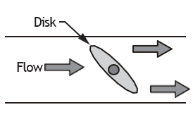
Valve Selection
When selecting a valve for a specific job, you will need to match the valve specifications to the job specifications. This is important to ensure dependable, long-term performance.
Before selecting a valve, consider the following factors:
- Operation cycle (number of times the valve will have to open and close)
- Specific purpose of the valve (to stop, regulate, divert, or relieve pressure)
- Pressure loss through the valve (pressure loss must be within system requirements)
- Expected flow volume of the system (must allow sufficient flow for system)
- Working and maximum pressures of the system (the valve characteristics should not be lower than those of the system)
- Working and maximum temperatures of the system (the valve characteristics should be the same or higher)
- Characteristics of the fluid being handled (for example, viscosity, volatility, corrosiveness)
- Presence of debris in the fluid (the valve’s capability to handle solids)
- Maintenance schedule (need for frequent maintenance may be a concern)
- Installation costs, maintenance costs and initial cost
- Exposure to the surrounding environmental conditions (for example, heat, freezing, physical damage and corrosive atmospheric conditions)
- Clearances for operation and maintenance
- Other specific job-related specifications and conditions, including any code requirements
Valve Specifications
Valves should be clearly marked with the manufacturer’s name and the size of the valve. Valves may also be marked with other information, such as the temperature and pressure ratings. Often letter codes are used to indicate the valve’s appropriate uses. Detailed service ratings are usually found in the manufacturer’s published specifications.
- G: gas service
- L: liquid service
- O: oil service
- S: steam service
- W: water service
The ability to read and interpret valve markings and specifications is key to installing the correct valve. Each manufacturer may have a different system of valve markings, which is explained in that manufacturer’s product literature. Following are examples of valve markings found on Crane valves.
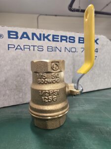
Figure 7a Example letter code on a crane valve (Audrey Curran/TRU Open Press) CC BY-NC-SA
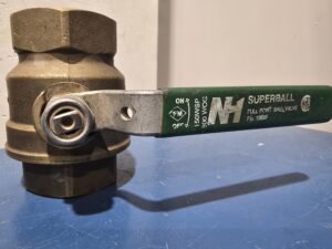
Figure 7b Example letter code on a crane valve (Audrey Curran/TRU Open Press) CC BY-NC-SA
| 2 | pipe size in inches |
| Crane | manufacturer |
| 125 | basic steam working pressure |
| 6 | pipe size in inches |
| Crane | manufacturer |
| Steel | carbon cast steel valve |
| 150 | basic steam working pressure |
Forged steel valves typically include the marking “Forged Steel.”
| 6 | pipe size in inches |
| Crane | manufacturer |
| Forged Steel | carbon cast steel valve |
| 150 | basic steam working pressure |
| 6 | pipe size in inches |
| Forged Steel | carbon cast steel valve |
| 150 WOG | working pressure water, oil or gas |
Tags may also be attached to the valve body or handle to indicate any approval ratings, such as an ASSE (American Society of Stationary Engineers) rating, etc.
Examples of Valve Specifications
On most jobs, you will install valves that have already been selected by the design engineer. On some jobs, however, you will need to select the correct valve yourself, using the manufacturer’s written specifications. You therefore must be able to read and interpret specifications such as those shown in the following tables. Note that these example tables are general in nature and are for the purpose of illustration. Always refer to the manufacturer’s specifications.
|
Test Pressures |
||
|
Body |
1.5 MPa (15 kg/cm2) (217.6 psi) |
2.4 MPa (24 kg/cm2) (348 psi) |
|
Seat & back seat |
1.0 MPa (10 kg/cm2) (145 psi) |
1.6 MPa (16 kg/cm2) (232 psi) |
|
Part No. |
Name of Part |
Material |
|
1. |
Body |
Bronze |
|
2. |
Wedge |
Bronze |
|
3. |
Stem |
High tensile brass |
|
4. |
Bonnet |
Bronze |
|
5. |
Stuffing box |
Bronze |
|
6. |
Gland packing |
Asbestos/Teflon |
|
7. |
Gland |
Bronze |
|
8. |
Gland nut |
Bronze |
|
9. |
Handwheel |
Cast iron |
|
10. |
Washer |
Mild steel |
|
11. |
Screw |
Mild steel |
|
Nominal Size |
Length (mm) |
Height (mm) |
Width (mm) |
Flange Diameter (mm) |
Flange Thickness (mm) |
|
|
Inches |
mm |
|||||
|
0.5″ |
15 |
72 |
102 |
58 |
95 |
6 |
| [latex]\frac{3}{4} \text{"}[/latex] |
20 |
76 |
115 |
58 |
105 |
6 |
|
1″ |
25 |
90 |
129 |
67 |
115 |
8 |
|
1.25 |
32 |
100 |
140 |
73 |
140 |
8 |
|
1.5″ |
40 |
110 |
162 |
85 |
150 |
9 |
|
2″ |
50 |
120 |
188 |
110 |
165 |
11 |
|
2.5″ |
65 |
140 |
220 |
110 |
185 |
13 |
|
3″ |
80 |
150 |
249 |
133 |
200 |
13 |
|
4″ |
100 |
190 |
292 |
173 |
220 |
16 |
Valve Actuator
A valve actuator is a device used to open, close or control a valve.
The types of valve actuators include the following:
- Handwheel: used to open or close a valve by turning it by hand (manually). No power is required.
- Pneumatic (air-operated) diaphragm: uses compressed air to move the valve open or closed. Air pressure pushes on a flexible diaphragm.
- Electric motor: uses electricity to turn the valve open or closed. It is often used when the valve needs to be controlled from a distance (remote control).
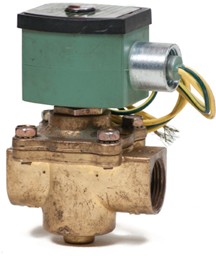
- Electric solenoid: uses electricity to create a magnetic force that moves the valve (electromagnetic force). It is usually used for quick on-off control.
- Hydraulic (piston-operated): uses pressurized oil or fluid to push a piston that moves the valve. It is used when a lot of force is needed.
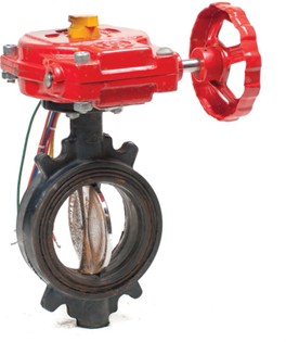
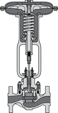
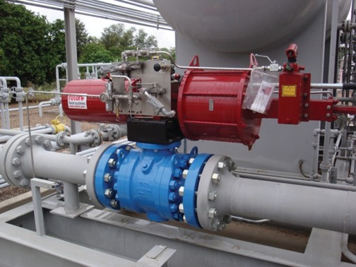
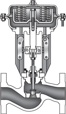
Pneumatically actuated globe valves are widely used for control purposes in many industries, although quarter-turn types such as (modified) ball and butterfly valves may also be used.
Principal Valve Types
Gate Valves
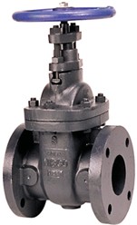
Gate valves are commonly used in industrial piping. This type of valve should only be used to fully stop or fully open the flow. The valve gets its name from the gate-like disk, which operates at a right angle to the path of flow. It is a linear movement valve.
The gate valve has the following characteristics:
- It is suited for wide-open (fully open) service.
- There is little resistance to flow when the disk is fully open.
- When the valve is closed tight, there is no wear or undue strain on the disk or seats.
- A partially open disk may cause turbulent flow, vibration, and chatter.
- A gate valve usually requires more turns to open and close fully.
Unlike many globe valves, the volume of flow through the valve is not in direct relation to the number of turns of the handwheel. Gate valves with wedge disks and matching tapered seats may be difficult to re-face or repair.
Advantages of using gate valves include the following:
- They have good shutoff features.
- They are bidirectional and therefore can be used in two directions.
- Pressure loss through the valve is minimal.
The major drawbacks of using gate valves are as follows:
- They cannot be quickly opened or closed.
- They are not suitable for regulating or throttling flow.
- Vibration and chattering can occur when a gate valve is left in a slightly open position with high-velocity turbulent flow. This can lead to wire drawing and erosion of seating surfaces.
- Repeated movement of the disk near the point of closure under a high-pressure flow may gall or score the seating surfaces on the downstream side. Galling can be minimized by decreasing contact stresses or by using protective surface layers.
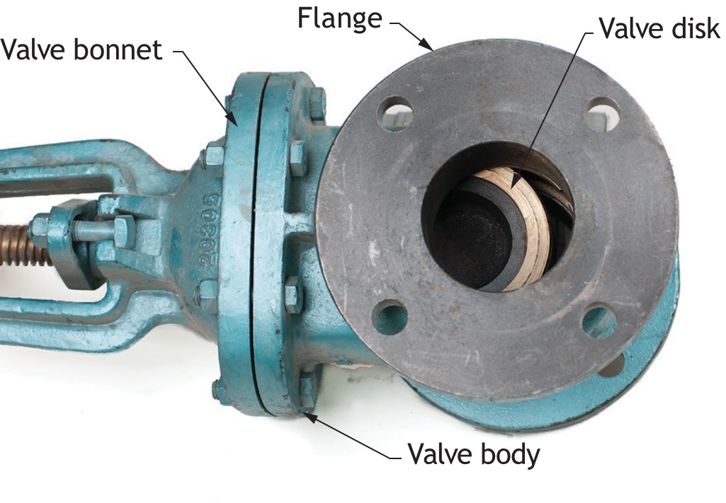
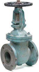
Gate Valve Parts
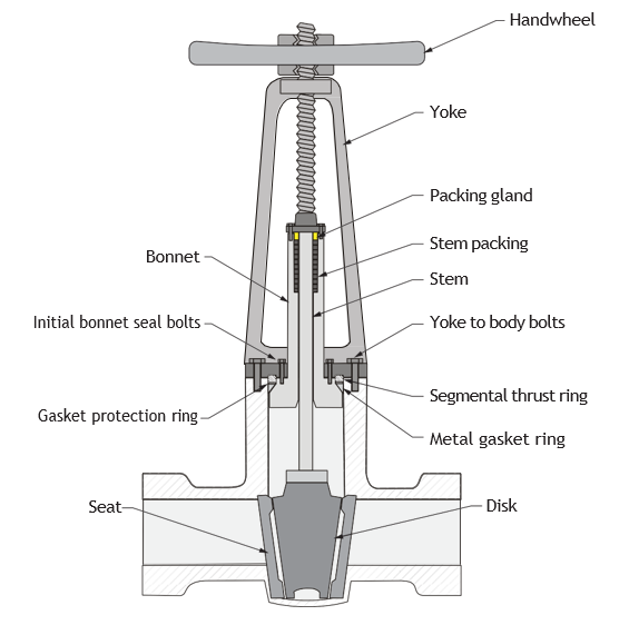
A gate valve consists of four main components:
- Body
- Bonnet (or cover)
- Disk/gate
- Stem
Other parts include:
- Handle (or wheel)
- Yoke
- Packing gland
- Packing
- Stuffing box
- Body seat rings
Gate Valve Seating and Disk Design
Gate valves are usually classified by the type of disk used.
The types of disks are:
- Solid wedge
- Flexible wedge
- Split wedge
- Parallel disk
Solid Wedge Disk
The solid wedge disk gate is wedge shaped, and it seats on corresponding faces in the valve body. The mechanical advantage of the valve stem threads together with the wedge angle provides the force for positive closure without excessive handwheel effort. The seat can sometimes be coated with Teflon Polytetrafluoroethylene (PTFE) to assist in a positive shutoff.
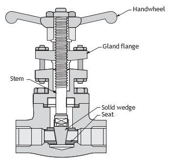
The solid wedge characteristics are that it:
- Consists of a strong and simply designed single part
- Can be installed in any position without danger of jamming due to misalignment of parts
- Ideal for service with steam, water, air, oil, gas and many other fluids
- Suitable for turbulent flow because there is nothing inside that can vibrate and chatter
- The disk may be subject to sticking under extreme temperature changes. For such conditions the flexible wedge disk is recommended.
Flexible Wedge Disk
The flexible wedge disk was developed especially to overcome sticking in high-temperature service with extreme temperature changes.
The flexible wedge disk characteristics are:
- Flexibility that allows the disk to be tight on both faces over a wide range of pressures
- No sticking during temperature changes
- Two disk faces that can move independently of each other, up to two full degrees.
- One-piece construction, so no loose parts to cause harmful vibration.
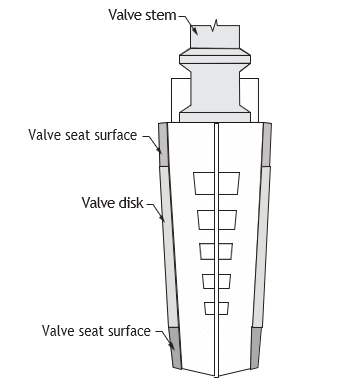
A problem associated with flexible wedge gates used on a steam system is that water tends to collect in the body neck. Under certain conditions, the admission of steam may cause the
valve body neck to rupture, the bonnet to lift off, or the seat ring to collapse. Following correct warming procedures will prevent these problems.
Gate valves used in steam systems have flexible wedges. The reason for using a flexible gate is to prevent binding of the gate within the valve when the valve is in the closed position. When steam lines are heated, they expand and cause some distortion of valve bodies. If a solid gate fits snugly between the seat of a valve in a cold steam system, when the system is heated and pipes elongate, the seats will compress against the gate and clamp the valve shut. This problem is overcome by using a flexible gate, whose design allows the gate to flex as the valve seat compresses it.
Split Wedge Disk
The split wedge disk is a two-piece wedge disk that sits between matching tapered seats in the valve body.
The split wedge characteristics as follows:
- A spreader device is simple and integral with disk halves.
- When closing, the last turn of the handwheel forces the disk against the seats.
- When opening, the first turn releases the disk from the seats.
- The split wedge gate is suitable for handling non-condensing gases and liquids at normal temperatures, particularly corrosive liquids.
- Freedom of movement of the disk in the carrier prevents binding even though the valve may have been closed when hot and later contracted due to cooling.
- The split wedge disk valve should be installed with the stem in the vertical upright position.

Figure 17 Split wedge gate valve (BC Industry Training Authority, 2019). CC BY-NC-SA 4.0
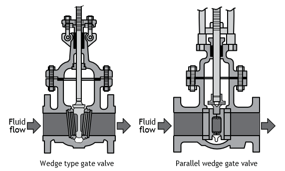
Parallel/Double Wedge Disk
The parallel or double wedge disk makes closure by moving between matching seats in the valve body. As the valve is being closed, upper and lower spreaders contact a stop. The disks are forced outward tightly against the seats. This type is widely used for water service, in waterworks and sewage disposal plants, and also in cross-country oil and gas pipelines. The parallel disk gate valve is designed to prevent valve binding due to thermal heating and cooling of the piping systems.
This design is used in both low- and high-pressure applications. Parallel disks are used in valves having parallel seats.
The parallel wedge disk characteristics are as follows:
- The first opening movement releases the disk from the seat.
- Exposure of a closed valve to a rise in external temperature may cause a dangerous increase in internal pressure, if non-compressible liquid is trapped between the disks.
- Repairing or re-facing is easier than it is on a tapered wedge disk.
- It is generally not suitable for steam. Rapid expansion and the high velocity of steam flow tend to vibrate loose internal parts in the disk assembly.
- It should be installed with the stem above horizontal for best results. Spreader mechanisms are subject to jamming when installed with the stem below the horizontal line.
In some parallel disk gates, the two halves do not move apart with a wedge action. Instead, the upstream pressure holds the downstream disk against the seat. A carrier ring lifts the disks, and a spring or springs hold the disks apart and seated when there is no upstream pressure.
Another parallel gate disk design provides for sealing only one port. In these designs, the high- pressure side pushes the disks open and forces the disk closed on the low-pressure side. With such designs, the amount of seat leakage tends to decrease as differential pressure across the seat increases. These valves usually have a marking that indicates the high-pressure side. Care should be taken to ensure that these valves are not installed backwards in the system.
Gate Valve Stem Operations
A valve stem connects the handle to the valve disk and transfers motion to open or close the valve. When selecting a valve, the type of stem can be important for:
- The need to indicate if a valve is in the open or closed position; for example, a rising stem
- Clearance requirements, such as restricted clearance above the valve; for example, a non-rising stem
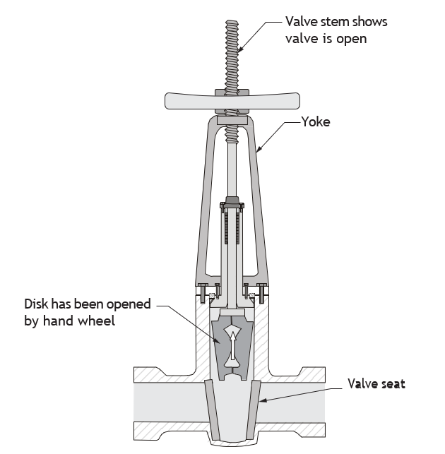
Rising Stem Valve with Outside Screw
A rising stem outside screw valve has stem threads on the outside of the valve body. The stem is then not subjected to damage caused by corrosion, erosion, sediment, or line fluids. Being outside, the stem threads can be lubricated easily when necessary. The position of the rising stem valve indicates whether the valve is open or closed. Turning the handle to open the valve causes the stem to rise up through the handle. The handle stays attached to the yoke. The outside screw and yoke valve (OSY) shown in Figure 19 is an indicating valve. When the valve stem is fully exposed above the handle, this indicates that the valve is fully open.
Rising Stem with Inside Screw
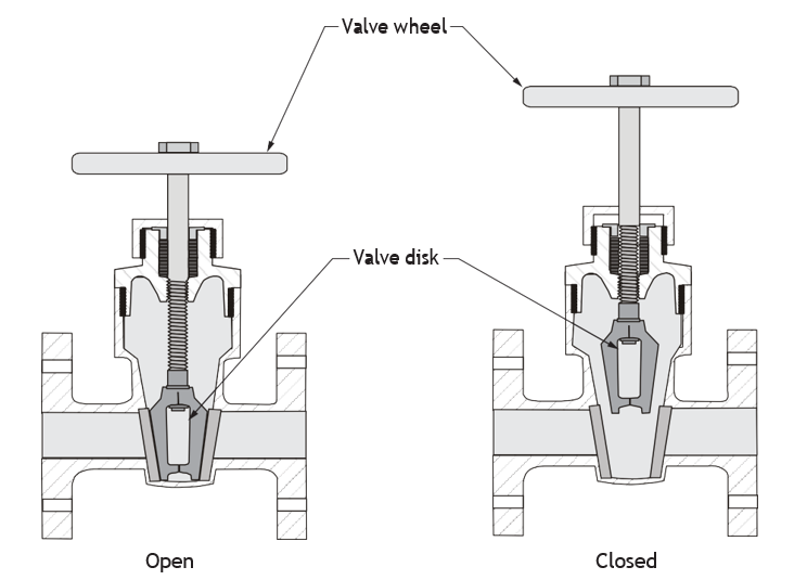
The rising stem inside screw valve is the simplest and most common stem construction for gate, globe, and angle valves in the smaller sizes. In these valves, the stem turns and rises on threads inside the valve. A close look at the position of the handwheel indicates whether the disk is open or closed (Figure 20).
The position of the valve is not as easily identified as the OSY valve.
Non-rising Stem with Inside Screw
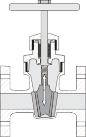
Generally used on gate valves only, this stem does not rise, but merely turns with the handwheel. The non-rising stem disk travels up and down on the threaded stem inside the valve body when the handwheel is turned. Since only the valve stem rotates, there is less packing wear. This valve is ideal for locations where headroom is limited.
Globe and Angle Valves
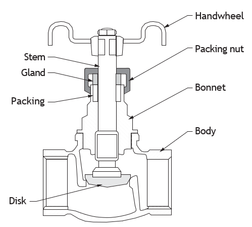
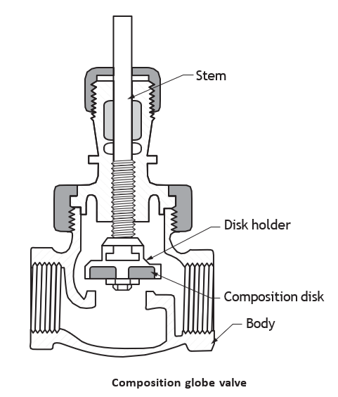
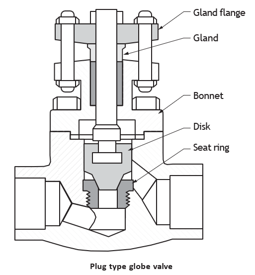
The globe valve is named after its globular body. The flow through a globe valve passes up under the seat, changing the direction of flow and thereby causing increased resistance and higher pressure loss than gate valves. Globe valves are best suited for throttling and flow control because of the seating arrangements.
The features of a globe valve are:
- Globe valve seating is parallel to the line of flow, unlike the right-angle seating in gate valves.
- All contact between the seat and disk ends when flow begins.
- The globe valve is efficient for throttling of flow.
- There is minimal wire drawing and seat erosion.
- The size of the seat opening is directly proportional to the number of turns of the hand wheel.
- The operator can gauge the rate of flow by the number of turns of the hand wheel.
- Plug-type globe valves permit close flow regulation.
- A shorter disk travel with fewer turns is required to operate globe valves.
- Globe valves save time and work.
- There is less wear on valve parts.
- Globe valves have fewer maintenance problems than gate valves.
- The seat and disk in most globe valves can be repaired without removing the valve from the pipeline.
Note: Globe valves are generally ideal for throttling, and are preferable for frequent operation.
Globe Valve Body Designs
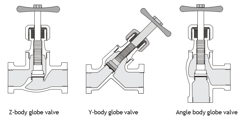
The three primary body design patterns for globe valves are:
- Z-body
- Y-body
- Angle body
The Z-body globe valve is the simplest globe valve design and is often used for water applications. The Z-body provides a symmetrical form that simplifies manufacture, installation and repair.
The Y-body globe valve reduces the pressure drop found in the Z-body and angle globe valves. The seat and stem are angled at approximately 45 degrees. A Y-body globe valve is suited for high- pressure and other severe services.
The angle body globe valve design allows the fluid to flow through with only one change of direction. A standard globe has two changes of fluid direction. An advantage of the angle valve is that it can function as both a valve and a piping elbow.
Globe Valve Disks
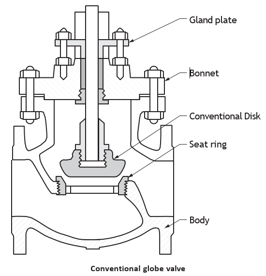
Globe valves are available with different shapes of disks or plugs:
- Conventional disks, which are often replaceable.
- Composition disks made of composite rubber type material; often replaceable.
- Plug disks, which are broad disks that provide more control under severe operating conditions.
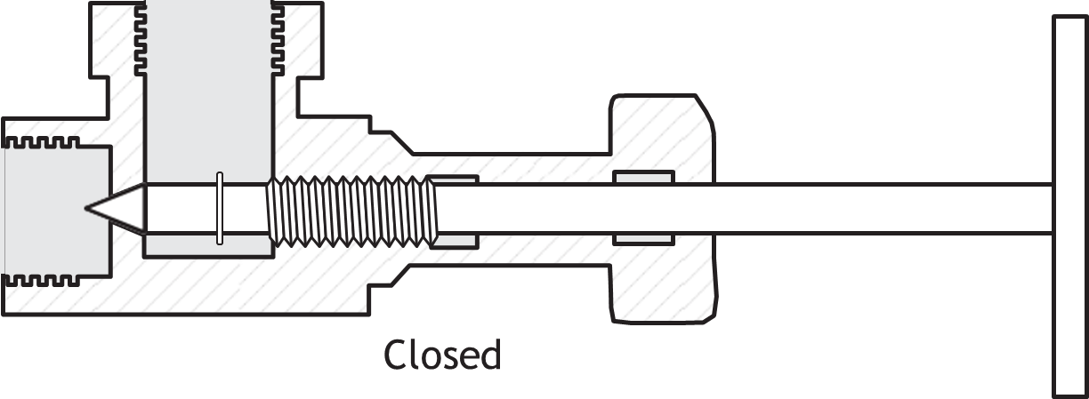
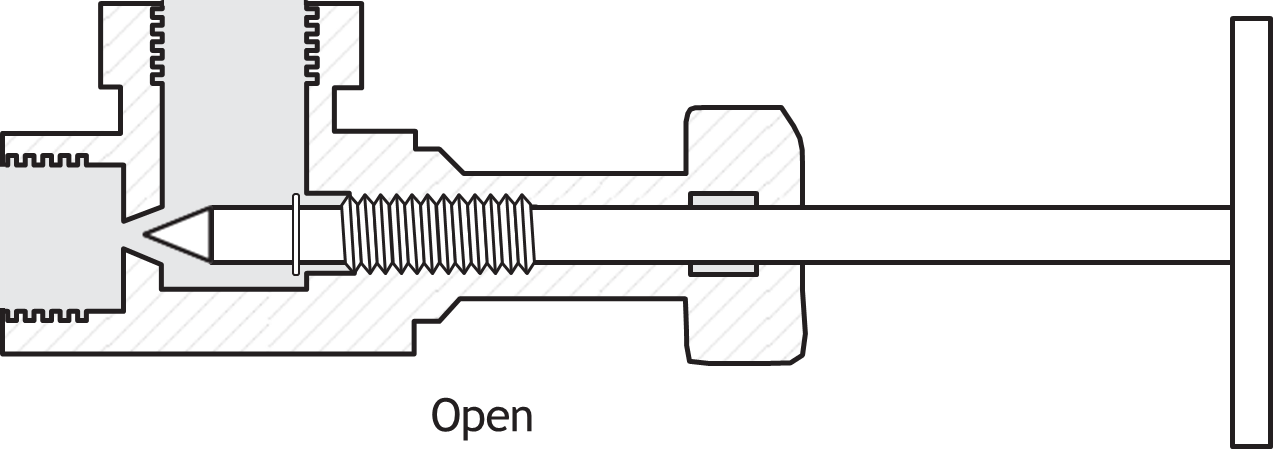
- Needle disks, used where fine throttling control is needed.
Plug Pattern Valve/Plug Cock
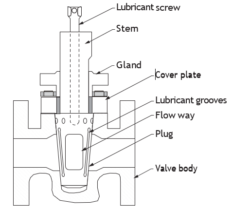
A plug valve is a quarter-turn rotational motion valve with a tapered or cylindrical plug that stops and starts flow. The plug has an angular hole in it that matches the diameter of the inlet and outlet of the valve. In the open position, the plug-passage is in line with the inlet and outlet ports of the valve body. If the plug is rotated 90° from the open position, the solid part of the plug blocks the port and stops the flow.
Advantages of using plug valves:
- Quick quarter turn on-off operation
- Minimal resistance to flow
- Smaller in size than most other valves
Disadvantages of plug valves:
- Requires a large force to actuate, due to high friction
- NPS 4 and larger valves requires the use of an actuator
- Reduced port, due to tapered plug
Plug valves come in a non-lubricated or lubricated design and with several styles of port openings. The port in the tapered plug is generally rectangular, but you can also get round ports and diamond ports.
Typical Plug Valve Uses
A plug valve can be used in many different fluid services, including:
- Air, gaseous and vapour services
- Natural gas piping systems
- Oil piping systems
- Vacuum to high-pressure applications
- Water service connections
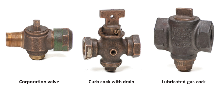
Typical types of plug valves include:
Plug valves are predecessors of today’s ball valves but can still be found in use as corporation fittings. The term “corporation” is used to describe valves and fittings of heavy brass or bronze construction that are manufactured to be capable of direct earth burial or exposed to the elements—in other words, heavy brass or bronze fittings that can be installed in harsh environments and that should last indefinitely. Corporation water valve locations can be on the city main under the street (street connection), at the property line (known as a curb stop) or on water meters. They are also used as shutoffs just upstream of a gas meter. Piping connections to corporation valves and fittings can be threaded, flared, or compression types.
Ball Valves
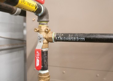
The ball valve gets its name from the ball-shaped disk located within the body. A hole through the centre of the ball allows the flow to go straight through, which is a characteristic of ball valves. Ball valves are used to control the flow of a wide variety of fluids in industrial, chemical, petrochemical, refinery, pulp and paper, gas transmission, water works and sewage, and power plants.
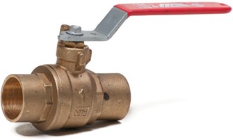
Ball valve features:
- Can be opened or closed with a quarter-turn of the operating handle
- Positive closure
- Handle position indicates the valve position as partially or fully open or closed
- Straight-through flow, minimum turbulence, low torque, tight closure and compactness
- Reliable operation, easy maintenance and long-life economy
Advantages of using ball valves:
- Quick, quarter-turn on-off operation
- Tight-sealing with low torque
- Smaller in size than most other valves
Disadvantages of ball valves:
- Poor throttling properties
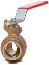
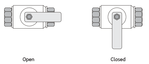
Ball Valve Function
Ball valves are best used for fast-acting stop/start applications. They are considered quick-acting because they only require a 90° turn of the handle to operate the valve. The quarter-turn minimizes valve operation time and decreases the possibility of leakage due to wear.
Ball Valve Types
Ball valve types include:
- Full port ball valve
- Standard and reduced port ball valves
- V-port ball valve
- Three port ball valve
A full port ball valve has an oversized ball, with the hole in the ball the same diameter as the inside of the pipe. This results in unrestricted flow and less friction loss. However, the valve is larger and more expensive, so this is only used where free flow is required.
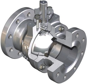
In standard port and reduced port ball valves, the ball opening is smaller than the pipe’s inner diameter, and so flow through the valve is reduced.
A V-port ball valve has either a V-shaped ball or a V-shaped seat. This allows the orifice to be opened and closed in a more controlled manner. When this valve is opened, the small end of the V-shaped ball opens first, allowing stable flow control during opening.
Butterfly Valve
The butterfly valve gets its name from the wing-like action of the disk, which operates at right angles to the flow. In the standard design, the valve stem runs through the disk, giving it a symmetrical appearance. In later designs, the stem is offset, so that the disk “cams” into the valve seat.
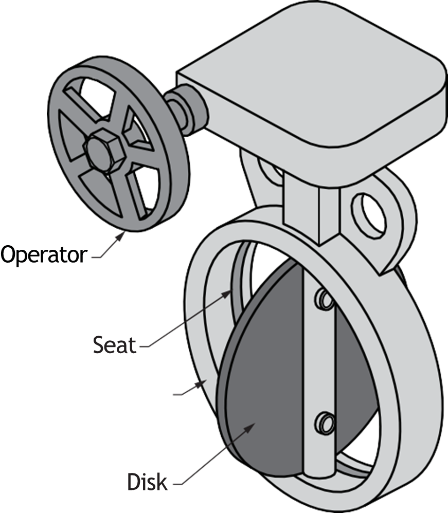
Butterfly valves are widely used in water distribution and waste water processing. Butterfly valves come in two body types, lugged and wafer. Wafer-style valves are common. Butterfly valves are an indicating-type valve. The position of the handle indicates the valve position as open or closed.
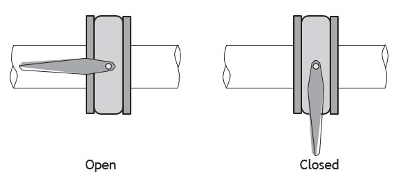
The butterfly valve is extremely durable, efficient, and reliable. The disk holds against a resilient liner to provide bubble tightness with low operating torque. The valve opens or closes with a quarter-turn of the operating handle, providing positive closure. The handle position indicates the valve position as partially or fully open or closed.
Advantages of butterfly valves:
- Compact design requires considerably less space than other valves.
- Light weight.
- Quick operation requires less time to open or close.
- They come in very large sizes.
- They have low-pressure drop and high pressure recovery.
Disadvantages of butterfly valves :
- Throttling service is limited to low differential pressure.
- Cavitation and choked flow are two potential concerns.
- Disk movement is unguided and is affected by flow turbulence.
Wafer-Type Butterfly Valve
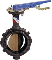
The wafer-type butterfly valve is designed for quick installation between pipe flanges. No gasket is needed because the moulded-in seat is lapped over into a recess in both faces of the valve body ends.
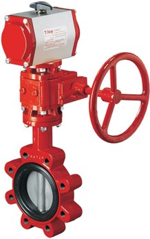
Wafer Lug Type Butterfly Valve
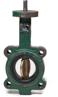
Wafer lug type valves have the same design as wafer-type valves, but include lugs in the body. These lugs can be threaded or non-threaded. The threaded lugs in a wafer lug type butterfly valve allow the upstream piping to be left intact while downstream piping is dismantled for cleaning or revamping.
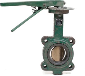

Butterfly valves can be supplied as manual gear operated, or with electric pneumatic or hydraulic operated actuators.
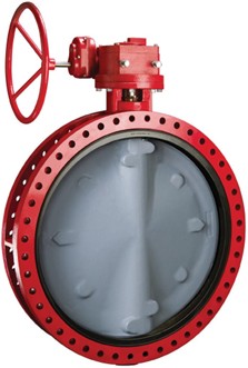
Double Flange Type Butterfly Valve
The double flange type butterfly valve differs from the wafer-type only in its body and seat design. A gasket may or may not be required as a seal between the pipe flanges and body flanges. Check the manufacturer’s specification.
Check Valves
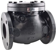
Check valves, also called non-return valves, automatically prevent the flow in a piping system from reversing direction. Sudden closure can produce water hammer, which will damage check-valve components. Small swing-checks generally have screwed caps, although some have bolted caps. The larger sizes have bolted caps or pressure- seal bonnets. Composition disks are common in small valves and in larger valves on water service. Seats in larger valves are often separate, although hard facing on integral seat and disk is also found.
The ideal check valve should have the following features:
- Open when upstream pressure appears
- Pass all flow in the normal direction without resistance
- Close at the instant of zero flow velocity
- Remain closed during minor forward pressure surges
- Resist backpressure without leakage
The two basic types of check valve are the swing-check and the lift-check. Other types include tilting disk check, wafer check and silent check.
Swing-Check Valve
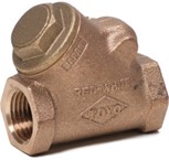
The swing-check valve with a single hanging disk is widely used. Swing-checks work automatically to prevent reverse flow. Valve bodies are either globe-like or a Y-form (also known as “wye”). The flow through swing-checks goes in a straight line, with low resistance to flow at the seat, similar to a gate valve. This similarity in effect on flow is the reason for generally using swing-checks in lines in combination with gate valves. Swing- checks are used for service at lower flow velocities and where pressure loss needs to be avoided.
Double-Disk Wafer-Type Check Valve
The double-disk wafer-type check valve, also called split disk or dual plate check valve, is a wafer pattern check valve designed to fit between two pipeline flanges. The split disk check valve requires less space for installation than standard swing-check valves. The split disk check valve is suitable for the prevention of reverse flow in pipelines carrying most types of liquids and gases, including fire sprinkler systems, steam and condensate lines.
The split disk wafer check valve employs two spring-loaded plates hinged on a central hinge pin. When the flow decreases, the plates close by the action of a torsion spring before flow reversal takes place, eliminating water hammer. It is a type of silent check valve.
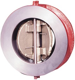
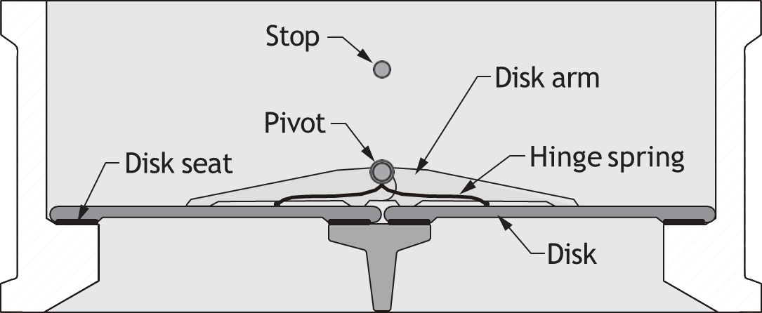
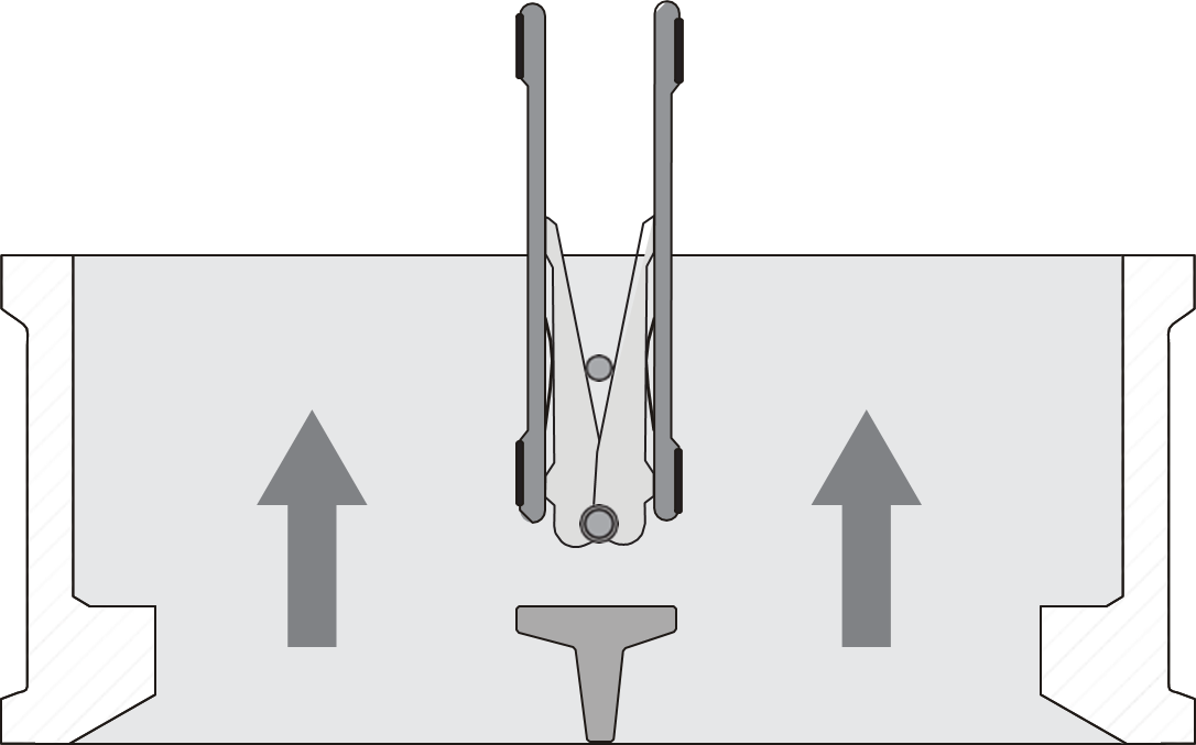
Sealing methods for these valves were originally developed for low-temperature water and petroleum-industry liquids, but metal-to-metal seals now allow the valve type to take up to 650°C at 13 410 kPa (1200°F at 1945 psi).
Tilting-disk Swing-Check Valve
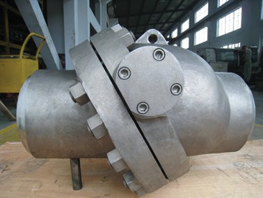
The tilting-disk swing-check valve is another variant of the basic swing-check valve. These valves have a disk that swings partly through the seat. The geometry for sealing and avoiding jamming is more complicated than for other swing-checks. The pivot shaft is generally large-diameter in tilting-disk valves, so attaching dashpots, indicators, and limit switches is easy. Access to the internals of some tilting-disk check valves, when they are mounted in the line, is through conventional bonnets or removable plates. The internals of other models are inaccessible, because the valve body is of the wafer or short-spool type.
Tilting-disk swing-check valves are generally made of plastic or stainless steel, the latter being the most widely used in chemical and petrochemical applications.
Lift-Check Valve
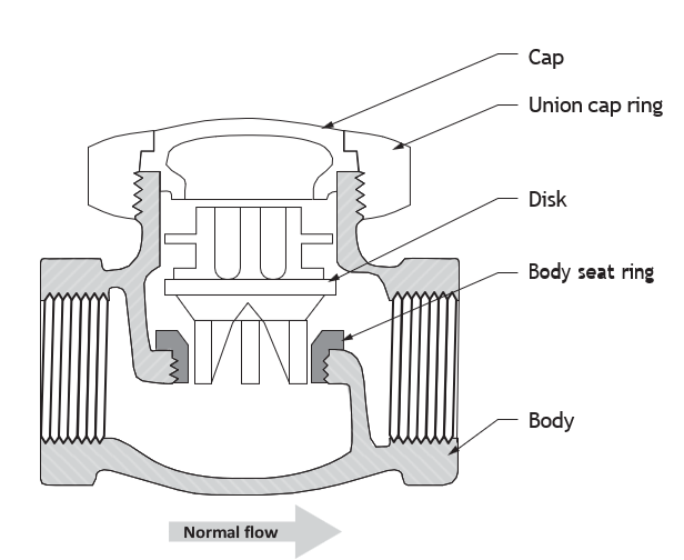
Lift-check valves operate automatically to prevent reverse flow. Lift-checks include the flat disk type, the plug-like disk type and ball-checks. The flow pattern through a lift-check is similar to that of the globe valve. Pressure losses in the lift-check are generally similar to those of a globe valve of the same size. The lift-check adapts well to pulsating service, even though not all lift-checks are recommended for this. The lift-check generally forces at least two right-angle turns on fluid flowing through it, so the pressure loss through it is higher than for a swing-check. Some in-line lift-checks have an improved flow path, with resistance nearly as low as the double-disk swing-checks. Traditionally, lift-checks are recommended for lines containing globe valves, which are high-resistance valves, or for lines carrying pulsating gases and vapours. A plug configuration disk is found in some lift-checks.
Bodies of lift-checks can resemble those of globe valves with either straight or Y bonnets. Bonnets can be screw cap, union cap, or pressure seal. The wafer form is common in silent lift-checks, but globular bodies and split, flanged bodies also appear.
Silent Flow Lift-Check Valves
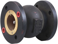
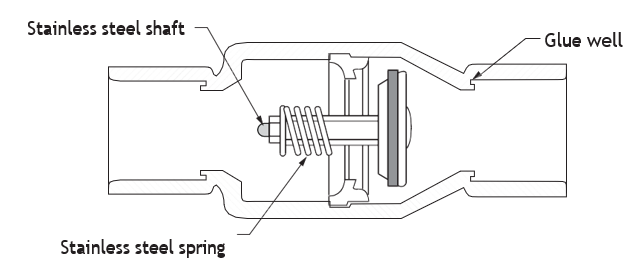
Silent flow check valves are used in commercial and industrial HVAC applications to prevent water hammer and reverse fluid flow in water lines with a maximum pressure of 2758 kPa (400 psi). Silent check valves have a low-pressure drop and can be installed in a horizontal or vertical position. The silent lift-check valve is often spring loaded. The spring prevents the check valve from slamming shut by closing the check valve either slightly before or at the instant of flow stoppage, thereby preventing water hammer. In systems where a pump is used, the silent check will not hammer when the pump stops.
Special-Purpose Service Check Valve (SVC)
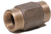
Service check valves are used in heating applications. They are installed between the boiler piping and system component. The service check facilitates the servicing of components under pressure, such as thermal expansion tanks and float vents, without draining the piping. As the component is threaded into the service check valve, the spring-loaded valve opens to system pressure. As the component is removed, the valve closes, maintaining system integrity while the component is being inspected. The service check is not to be used on safety relief valves or other safety or flow- sensitive components.
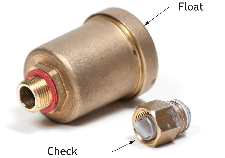
Installation of Service Check Valves
Install the service check on the system component, whether it is an expansion tank, float vent, pressure gauge, etc. Check to be certain the spring-loaded check valve opens, and then install the component with the service check into the system piping.
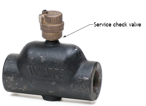

Removing System Components
System pressure must be reduced to atmospheric pressure, and the contained liquid must be allowed to reach the ambient temperature before removing any component attached to this valve. Failure to follow this procedure can result in the sudden release of hot or pressurized fluid, which may cause serious injury (such as burns), damage to equipment, or loss of system control.
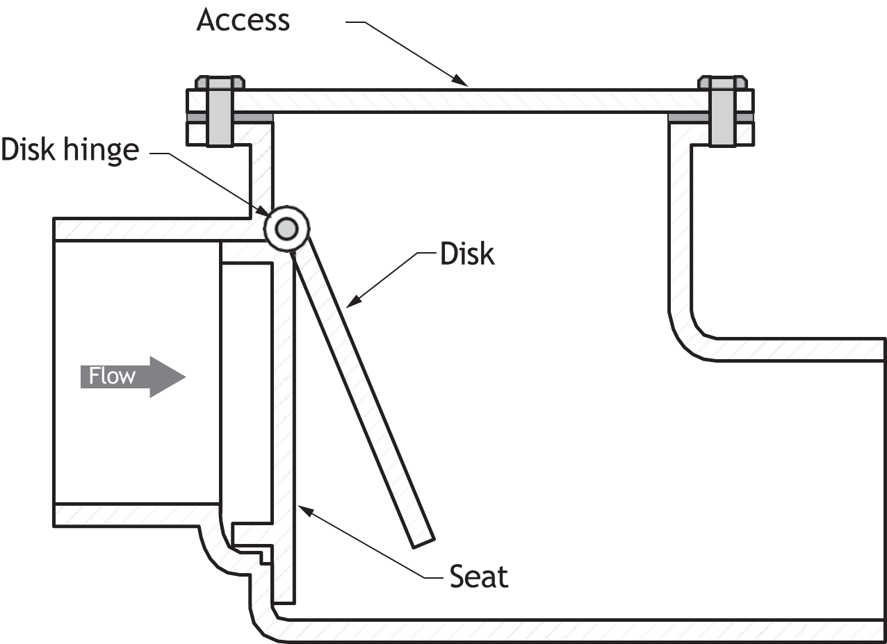
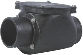
Backwater Valve
Backwater valves are check valves that prevent backflow in a sanitary drainage system or storm water system. Backwater valves prevent flood damage to lower floors in a building.
Special-Purpose Valves
Knife Valves
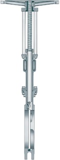
Knife valves are gate valves specially designed for tough applications. They are used in the food, cement, and pulp and paper industries, and in power-plant, chemical and slurries applications. The gates can be made of stainless steel and other alloys. They can slice through the handled fluid types to provide a positive shut-off.
Combination Valves
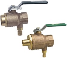
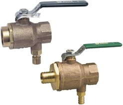
Combination ball valve and relief valves are used for applications that require a means to shut off the water supply to the water heater, and for providing protection from excess water pressure caused by thermal expansion. Combination valves may appear in commercial and residential applications on water heater installations.
Bypass Valves
Bypass valves are usually identified as valves placed on a piping arrangement called a bypass.
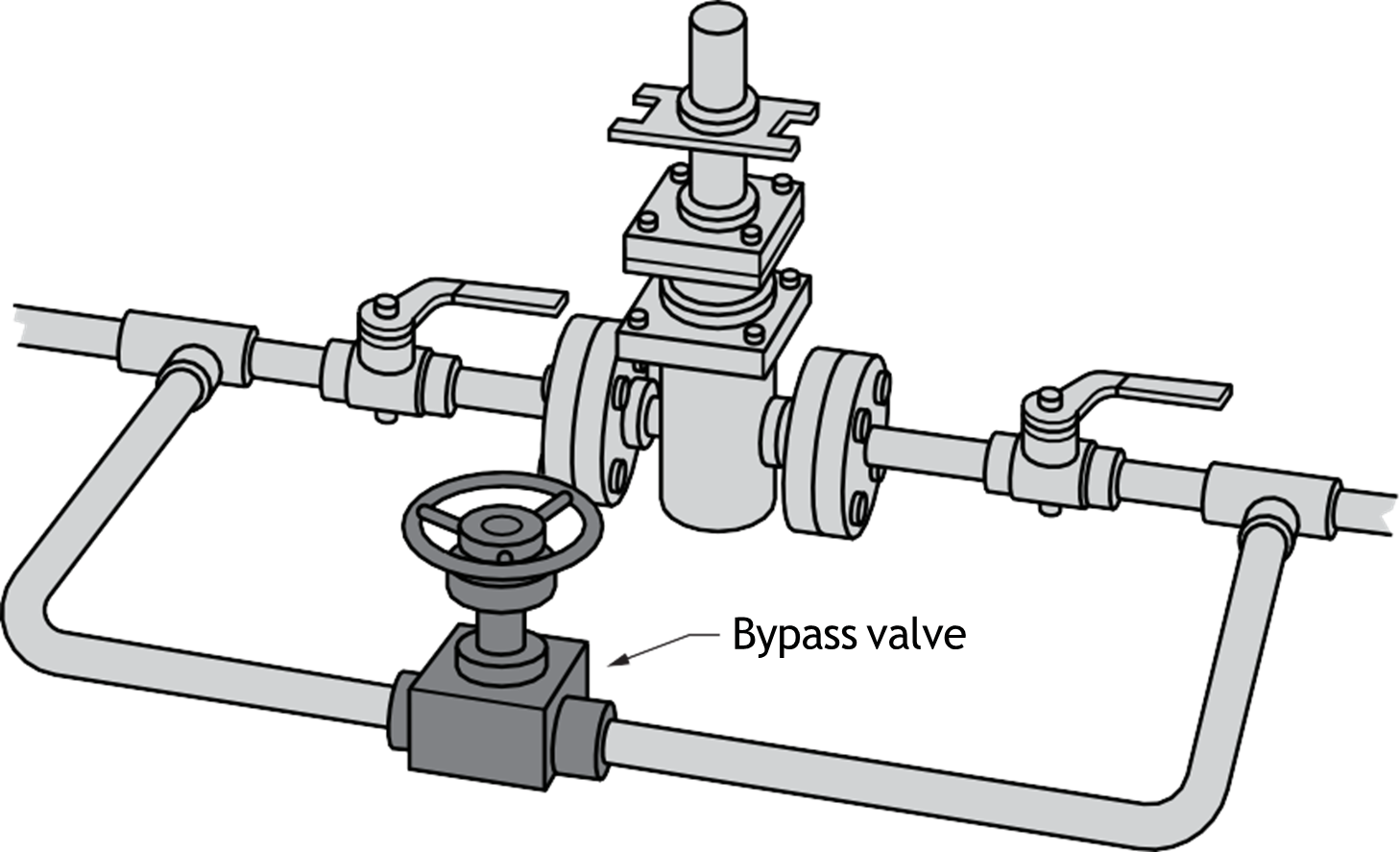
A bypass valve can control the fluid flow when the main valve is shut down for maintenance. The bypass valve may be used around equipment or pressure-reducing valves. The bypass can act as a quick fill in some cases or to divert flow, such as in a water treatment system. The type of valve used in the bypass depends on whether it will be used to open, close or adjust the flow. A globe valve bypass valve would provide some flow control. A gate valve or ball valve bypass valve would serve to stop flow rather than regulate the flow.
Stop and Waste Valves and Drain Valves
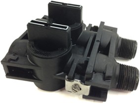
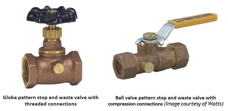
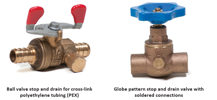
Stop and waste valves are specialty valves that serve as on and off shutoffs. They have a drain cap on the upstream side of the shut-off. Stop and drain valves allow the system to be drained for winterizing or repairs. Both types of valve are available with several different connection types (Figure 59).
Diaphragm Valve
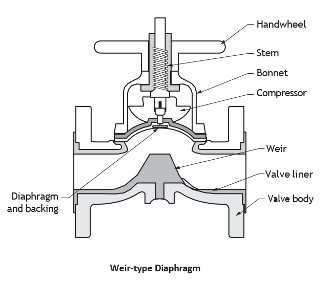
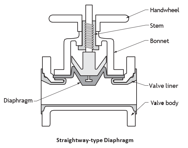
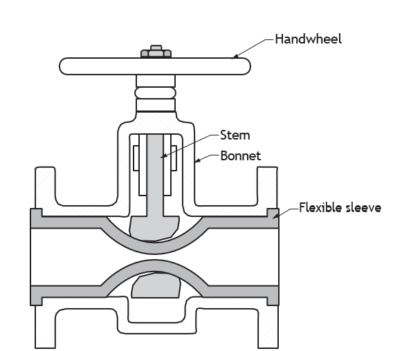
Diaphragm valves are used for corrosive and abrasive applications with 100% leak-tight operation. The valve stem and components are separated from the fluid by the diaphragm.
Diaphragm valves may be used for slurries (where other valve designs might clog) and in hygienic applications.
Pinch Valve
Pinch valves are suited for applications in which slurries or liquids contain large amounts of suspended solids. Pinch valves seal by pinching a flexible element such as a rubber tube.
Multiport Valves
Three-Port Mixing and Diverting Valves
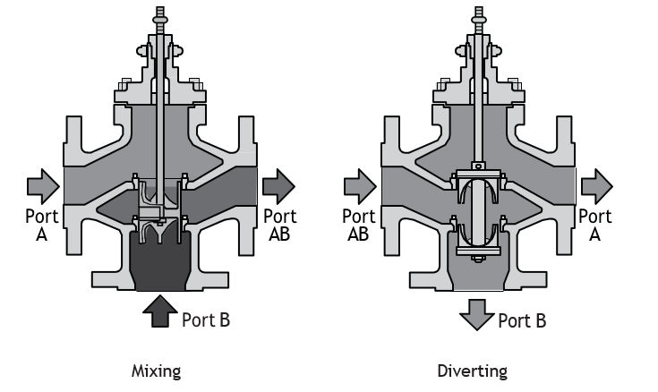
Three-port valves can be used for either mixing or diverting service, depending upon the piping arrangement. Valves similar to these types of valves are used on hydronic heating systems and domestic hot water systems.
Mixing valves and diverting valves can be easily distinguished visually by inspecting the piping arrangement:
- The mixing valve has two inlets and one outlet.
- The diverting valve has one inlet and two outlets
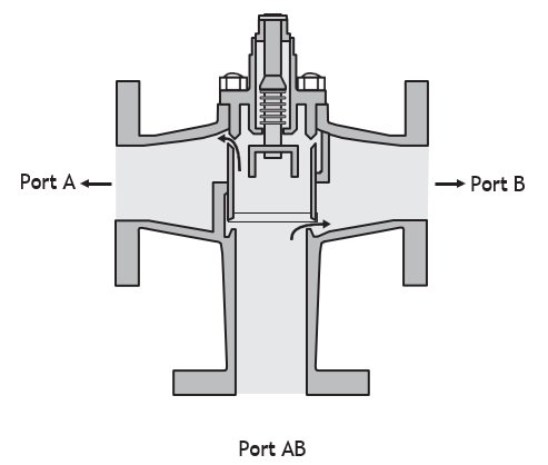
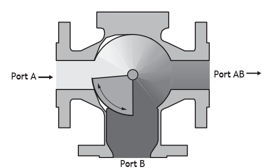
There are three basic types of three-port valve:
- Piston valve type
- Globe, plug type
- Rotating shoe type
Hot Water Temperature Control Valves
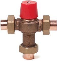
Thermostatic mixing valves maintain and limit mixed hot water to a desired, selectable temperature. Hot water temperature control valves are used in commercial, residential, and institutional applications to reduce the temperature of the hot water supply, thereby minimizing the risk of thermal shock and scalding to those using the water.
Double Block and Bleed Valves
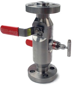
Double block and bleed valves have evolved to replace the process of bolting together individual valves to provide dual isolation. The block and bleed valve manifold is used to isolate or block the flow of fluid in the system. A block and bleed valve would be used to stop the flow of fluids to some component. Fluid would be vented from that component’s side of the manifold to allow maintenance.
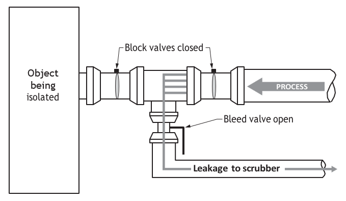
This configuration is often required to isolate high-pressure sections of a system to facilitate safe maintenance, etc.
Post Indicator Valves
A post indicator valve is little more than a gate valve, usually installed underground, that has an indicating post attached to the valve riser above ground to show whether the valve is open or closed. The valve is often used for underground fire protection lines.
Pressure Relief Valves
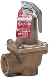
The pressure relief valve (PRV) is a type of safety valve used to control or limit the pressure in a piping system or components. The PRV opens when the pressure in the system reaches the relief valve pressure set point. The pressure relief set point is usually set below the maximum design limits of the piping system components or pressure vessel. PRVs can be preset by the factory for a specific purpose or they can be adjustable. Adjustable PRVs should be set at least 25% higher than system pressure but below the maximum pressure limit of the system components.
Regulations require PRVs on specific piping systems and pressure vessels. PRVs are typically required on domestic and commercial hot water storage heaters, heat exchangers, hydronic heating systems, compressed air systems, and other pressure vessels where safety pressure relief is required.
Spring Relief Valve
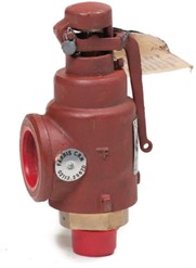
The most common type of relief valve is the spring relief valve, also called a pop safety valve, because it opens and closes suddenly. Spring relief valves use the tension of a spring to withstand internal pressure in a pipe. A sudden increase in pressure will force the spring open, and pressure will vent. As the pressure level drops, the spring forces the valve closed.
Thermal Expansion Relief Valve
Thermal expansion relief valves are used to relieve excessive pressure caused by thermal expansion of water. Thermal expansion relief valves are used when hot water storage heaters are installed, especially when the water service has a check valve or backflow preventer installed.
Temperature and Pressure Relief Valves (TPRV/T&P)
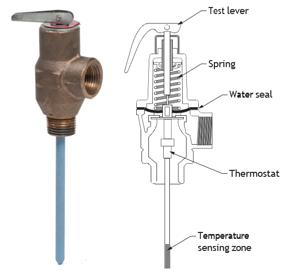
Combined temperature and pressure relief valves (TPRV/T&P) provide fully automatic protection against both excessive temperature and pressure in an emergency condition. They are required on all hot water storage type heaters and are set to relieve at 1034 kPa (150 psi) and 99°C (210°F).
Vacuum Relief Valves
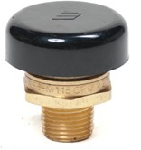
Vacuum relief valves allow air to enter the system to prevent negative pressure (lower than atmospheric) from developing in the tank. Vacuum conditions could siphon the water from the system, causing the tank or water heater to collapse or equipment to burn out.
Vacuum relief valves are found on the cold water inlet lines of domestic hot water supply tanks and heaters.
Applications of vacuum relief valves:
- Domestic water heaters and supply tanks
- Tabletop heaters
- Jacketed steam kettles
- Unit heaters
- Low-pressure steam systems
- Steam coil heaters
Note: A vacuum relief valve is not a backflow preventer.
A vacuum relief valve should be installed on the following:
- Domestic hot water heaters
- Supply tanks
- Unit heaters
- Steam kettles
- Other equipment where a vacuum could cause damage
Pressure Reducing Valves/Regulators
Water pressure reducing valves are used in commercial, industrial and residential applications to reduce incoming water pressure for protection of plumbing system components and to reduce water consumption. Water supply utilities use pumps and pumping stations to increase pressure in water mains to sufficient levels to supply water for firefighting, to overcome loss of pressure in the upper floors of high-rise buildings and to supply water towers and supply tanks. Pressure in water supply mains can exceed 1380 kPa (200 psi).
Most plumbing codes require water pressure reducing valves on domestic systems where the municipal water main’s pressure exceeds 551 kPa (80 psi). Higher pressures could rupture pipes, damage fixtures, and cause personal injury. Pressure-reducing valves can greatly reduce the effects of water hammer. They are available within specified pressure ranges and are adjustable within the specified ranges.
Two types of water pressure reducing valves are:
- Direct acting
- Pilot operated
Direct acting and pilot operated pressure reducing valves both use globe or angle-pattern bodies. Valves used on smaller piping diameter units are usually cast from brass; larger piping diameter units are made from ductile iron.
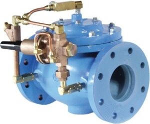
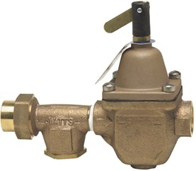
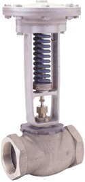
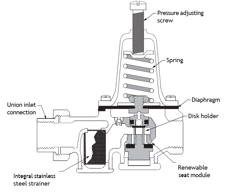
Direct acting pressure relief valves consist of globe-type bodies with a spring-loaded, heat-resistant diaphragm connected to the outlet of the valve that acts upon a spring. This spring holds a preset tension on the valve seat installed with a pressure equalizing mechanism for precise water-pressure control.
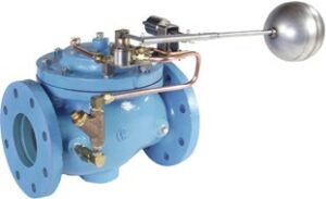
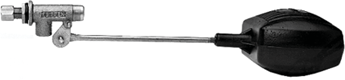
Float-Control Valves
Float-control valves are designed to automatically maintain a constant liquid level in a tank or reservoir. Mechanical float valves are used in commercial, industrial and agricultural applications to control high-capacity water flow. Mechanical float valves can be mounted on the tank wall.
Float-control valves can be controlled by ball floats or by remotely mounted sensing devices. A decrease in reservoir level causes the valve to move toward an open position, allowing the reservoir level to increase. An increase in reservoir level causes the valve to move toward a closed position, allowing the reservoir level to decrease.
The two float-control valves you are likely to encounter are the float-control valve in a water closet tank and the float-control valve in a water storage tank of a rural water supply system.
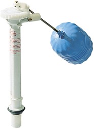
Toilet fill valves and thermal expansion relief valves are triple-function devices that consist of a toilet tank fill valve, an anti-siphon backflow preventer, and a thermal expansion pressure relief valve. This assembly is adjustable to fit all standard toilet tanks and performs the following functions:
- Limits the domestic water system’s pre-set static pressure
- Protects the temperature and pressure relief valve on the water heater
- Reduces the requirement for a thermal expansion tank or an auxiliary relief valve
- Prevents backflow from water closets.
Sliding-Stem Valves
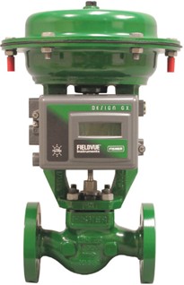
The sliding-stem valve’s body actuates with a linear motion using a manual lever or actuator rather than a handwheel, and there are no stem threads. Sliding-stem valves are available in both gate and globe valve designs. The sliding-stem valve is useful where quick opening and closing are needed.
Most sliding-stem control valves are direct acting, which means the valve opens up wider as the stem is drawn out of the body and closes when the stem is pushed into the body.
Backflow Preventers
Cross-connection means the contamination of a potable drinking water piping system by a non-potable substance. Preventing contamination of the potable drinking water distribution system is achieved through cross-connection control. A backflow preventer is a valve specially designed, tested and approved to prevent or eliminate cross connections.
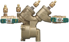
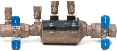
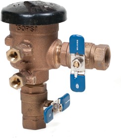
A backflow preventer may consist of any or all of the following: shutoff valves, test valves, relief valves, or air inlet valves. A backflow preventer may come as an assembly that has been tested and approved as a single unit. It should not be altered or replaced with field-constructed valves.
Types of backflow preventers include the following:
- Reduced pressure backflow assembly
- Double check valve assembly
- Pressure vacuum breaker assembly
Backflow Prevention Devices
Backflow prevention devices also prevent or eliminate cross connections of a lower risk level.
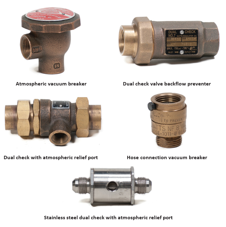
Valve Components and Materials
Valve Seat Ring
A seat ring is a part of the valve body assembly that provides a seating surface for the closure member. The seat ring provides a stable, uniform and replaceable shutoff surface. The seat rings may be threaded, pressed or machined into the valve body. Seat rings are typically bevelled at the seating surface. This allows the valve disk to be guided during the final stages of closing the valve. Some valve seats can be resurfaced in place with seat resurfacing tools when practical or economically suitable.
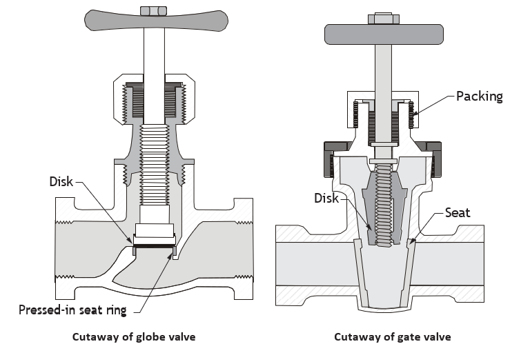
Types of Seating Materials
The material selected for valve seats and disks depends on the temperature, pressure and type of the fluid being controlled.
Factors to consider when selecting valve seating material include:
- Capability for replacement or resurfacing
- Hardness and resistance to wear, corrosion, erosion, galling, seizing and temperature
Valve seats can be made for relatively low pressure and temperatures and for ordinary fluids. They can be made of the following materials:
- Bronze or bronze-faced seating for bronze valves
- Iron surfaces may have iron or bronze seats
- Non-metallic composition disks such as Teflon
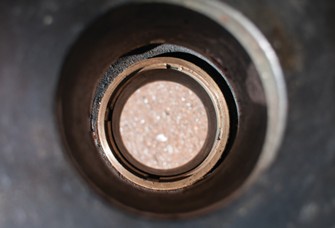
Teflon Polytetrafluoroethylene (PTFE)
PTFE is almost totally insoluble and chemically inert. It has high temperature resistance. Teflon PTFE ball seats require no lubrication because of natural lubricity. Teflon PTFE diaphragms and flange gaskets are used in the most severe chemical resistance applications.
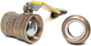
Ethylene Propylene Diene Monomer (EPDM)
EPDM is a synthetic rubber used as the standard seal material for some valves. It has excellent chemical resistance on the great majority of applications, including acids, alkalis and salts at temperatures up to 90°C (194°F). EPDM is weak on organic compounds and cannot be used on oils and fats.
Fluorocarbon Rubber (FKM or FPM) (Viton)
FKM/FPM is more expensive than EPDM, and so is used as an alternate when required. It has excellent resistance to mineral acids, oils and many aliphatic and aromatic hydrocarbons. FKM/ FPM is weak on sodium hydroxide. FKM-C is a special formulation with higher resistance to chlorine services. FKM-F offers better chemical resistance on inorganic acids than standard FKM.
Chlorinated Polyethylene (CPE)
CPE is superior for sodium hypochlorite handling than other elastomers. It resists hypochlorite up to a full strength of 13%.
Nitrile (Acrylonitrile-Butadiene Copolymer, NBR)
Nitrile is also known as Buna-N. It has high chemical resistance to oil and petroleum but is weak on oxidizing media (i.e., acids). Nitrile has excellent abrasion resistance and is less expensive than FKM/FPM.
Basic Stuffing Box Designs
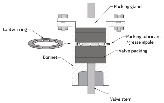
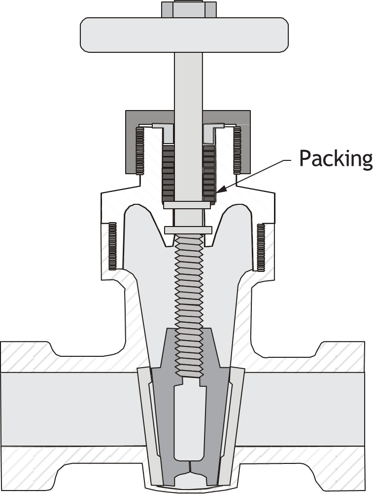
A stuffing box must provide an enclosure—a tight seal around the stem to retain pressure inside the piping system. The packing is placed in the stuffing box around the stem and held in place by a packing gland and/or nuts. The seal must be tight without binding the stem. Packing is subject to wear and must be periodically compressed and eventually replaced.
Packing that is too tight can cause the operation of the valve to be stiff. If tightening down on the packing gland nuts does not stop the leakage or causes the valve operation to be stiff, the packing should be replaced.
In some larger valves, a lantern ring is inserted between the turns of packing and is placed opposite to a lubrication point where grease can be injected to ease the valve operation.
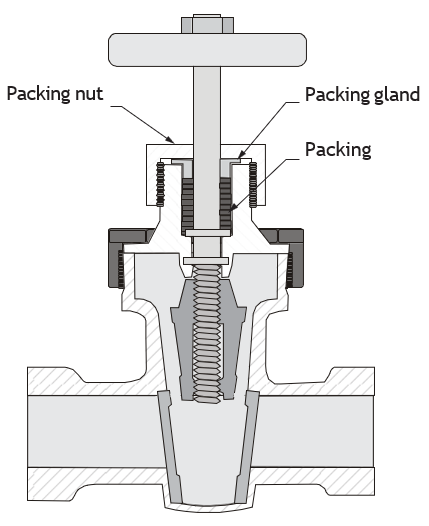
Valve Stem Packing
Valve packing provides a seal between the system fluids and the valve stem. The selection and installation of valve packing material provides positive and long life. Excessive tightening of a packing nut can apply excessive pressure against a valve stem, making the valve difficult to operate and reducing packing life. Check the manufacturer’s directions for torque values and procedures. If no specific instructions are available, the proper amount of packing torque to apply is that which results in a tight seal with the least amount of friction against the valve stem.
Packing Materials
Packing is made of different types of material depending on the manufacturer’s specification for the valve and the intended service conditions. Examples of packing materials include:
-
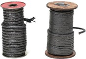
Figure 92 Compression-braided packing (BC Industry Training Authority, 2019). CC BY-NC-SA 4.0 Graphite l
- Teflon (PTFE)
- Spun synthetic fibre
- Glass fibre optic glaze (GFO fibre)
- Compression-braided packing (see below)
- Combinations of the above
Generic Packing Replacement Procedure
When packing needs to be replaced, avoid adding new packing to old. Remove all old packing and replace with new packing material. Following is the general procedure:
- Examine the valve.
- Loosen the packing gland to release any trapped pressure.
- Remove all old packing and thoroughly clean the shaft/stem and stuffing box area.
- Examine the shaft/stem for corrosion, nicks, scoring and excessive wear.
- Examine other components for burrs, cracks and wear that could reduce packing life.
- Check the stuffing box for excessive clearances and the shaft for straightness.
- Replace any components found defective.
- Inspect the old packing as part of failure analysis for clues as to the cause of premature packing failure.
Prepare and Install Braided Packing
Always refer to the packing manufacturer’s instructions. Ensure the equipment and packing are clean before proceeding.
- Select the specified packing.
- Examine the packing to be sure it is free from defects.
- Wind the packing around a properly sized mandrel, or use a calibrated packing ring cutter.
- Cut the packing ends cleanly, square or diagonal, according to the packing manufacturer’s instructions.
- Cut one ring at a time, assuring that rings are sized precisely to the shaft or stem.
- Carefully install the packing rings one at a time. Ensure the cut ends are staggered so no easy pathway may be found.
- Install the packing nut or packing gland and nuts if used.
- Torque the packing nuts to the manufacturer’s specifications. If no specifications are available, do not overtighten the nuts.
- Tighten the nuts evenly to provide easy operation of the valve stem and a tight seal.
- Test the valve under operating conditions.
Bonnet Characteristics of Gate, Globe and Angle Valves
The bonnet is the portion of the valve that contains the packing box and stems seal, and can guide the stem. It provides the principal opening to the body cavity for assembly of internal parts, or it can be an integral part of the valve body. It can also provide for the attachment of the actuator to the valve body. Typical bonnets are bolted, threaded, welded, pressure-sealed or integral with the body.
There are many types of valve bonnet. The three most common types are:
- Screwed-in bonnet
- Screwed union ring bonnet
- Bolted bonnet
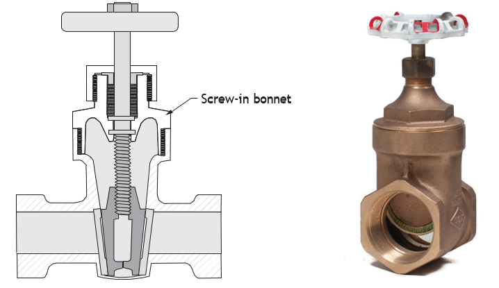
Screwed-in Bonnet
The screwed-in bonnet is used on bronze gate, globe and angle valves, where frequent dismantling is not needed. The bonnet screws into the valve body, rather than over the matching threads of a valve body. The screwed-in bonnet makes a durable, pressure-tight seal, suited for many services.
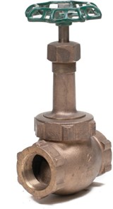
Screwed Union Ring Bonnet
The union bonnet is ideal for smaller size valves. The union bonnet provides relatively easy access to the valve parts for inspection or maintenance. The union bonnet ring is easily screwed or removed from the valve body, providing a tight seal.
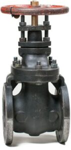
Bolted Bonnet
The bolted bonnet is used for larger valves or for higher pressure applications. The bonnet is adaptable to all types of gaskets. Multiple bolting permits equal sealing pressure without using excessive torque.
Lip-Seal Bonnet
The lip-seal bonnet and the valve body are screwed together until a firm metal-to-metal contact is made between the machined surfaces of the bonnet and the top of the body. One type of this bonnet is screwed and fillet welded to the valve body. Dismantling is accomplished by grinding off the fillet weld and unscrewing the bonnet. This valve is designed for high pressure and temperature services.
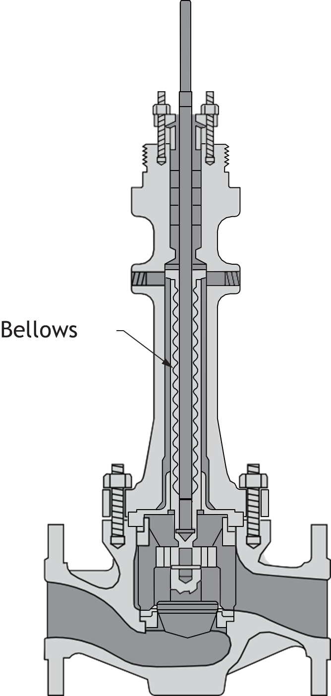
Bellows Seal Bonnet
A bellows seal bonnet is a bonnet that uses a bellows for sealing against leakage around the valve stem.
Pressure-Seal Bonnet
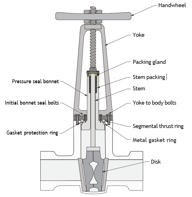
The pressure-seal bonnet is a newer style that is effective for sealing high pressures and temperatures. A pressure-seal bonnet utilizes line fluid pressure to seal the joint. As the line pressure increases, the bonnet seal gets tighter. The actual seal is at the contacting area of a wedge-shaped metal ring, making a pressure-tight metal-to-metal joint.
 Self-Test D-2.1: Describe Basic Valve Types
Complete Self-Test 2.1 and check your answers.
If you are using a printed copy, please find Self-Test D-2.1 and Answer Key in the Appendix at the end. If you prefer, you can scan the QR code with your digital device to go directly to the interactive Self-Test.

References
BC Industry Training Authority. (2019). Piping trades apprenticeship program: Use Tools and Equipment—Level 1 harmonized [Binder]. Crown Publications, Queen’s Printer for British Columbia. https://www.crownpub.bc.ca/Product/Details/7960000261_S
- Plumber: Competency D-4 Install Valves
- Steamfitter: Competency D-1 Install Valves
- Sprinkler Fitter: Competency D-4 Install Valves
Media Attributions
All figures are sourced from Industry Training Authority (2019) and/or Camosun College (2019) and are used under the Creative Commons Attribution 4.0 (CC BY 4.0) licence unless otherwise noted. Images copyrighted by the BC Industry Training Authority are licensed under a Creative Commons Attribution-NonCommercial-ShareAlike 4.0 (CC BY-NC-SA 4.0) licence.
- Figure 1 High pressure air valve by Peter Southwood on Wikimedia Commons is used under the CC0 1.0 public domain license.
- Figure 2 Ball valve by (Bitjungle/Wikimedia Commons) CC BY-SA 4.0
- Figure 3 Bidirectional tight butterfly valve (Heather Smith/Wikimedia commons)
- Figure 4 Pl control valve (Rafał Rygielski/Wikimedia Commons)
- Figure 5 Diverter valve with PEX connections by (Tomwsulcer/Wikimedia Commons) CC0 1.0
- Figure 6 Valve (NVgt156/Wikimedia Commons) CC BY-SA 4.0
- Figures 7a and 7b are by Audrey Curran/TRU Open Press and are subject to the CC BY-NC-SA license.
- Figures 22 Flanged gate valve, non-rising stem, and Figure 36 Wafer-type butterfly valve, is courtesy of NIBCO INC. Used with permission.
- The following figures are courtesy of Watts and are used with permission:
- Figures 42 Flanged T pattern iron body swing-check
- Figure 44 Split disk wafer check valve
- Figure 48 Flanged silent check valve
- Figure 54 Cast iron backwater valve
- Figure 56 Combination ball and relief valves
- Figure 70 Thermal expansion relief valves
- Figure 74 Direct acting water pressure regulator with strainer
- Figure 75 Steam pressure regulator
- Figure 78 Float valve, float arm and ball float
- Figure 79 Toilet fill valve and thermal expansion relief valve
- Figure 82 Reduced pressure backflow assembly
A valve used to fully open or fully close flow by raising or lowering a flat gate inside the pipe. (Section D-2.1)
Valves where the internal parts move in a straight line to open or close the flow. (Section D-2.1)
A valve with threads located outside the valve body, where the stem moves up and down as the valve is opened or closed, making it easy to see the valve position. (Section D-2.1)
A valve with a stem that moves up and down outside the valve body, making it easy to see if the valve is open or closed. (Section D-2.1)
A valve where the stem moves up and down inside the valve body as it turns, showing whether the valve is open or closed. (Section D-2.1)
A valve used to control or regulate flow by moving a disk against a seat inside the valve. (Section D-2.1)
The simplest globe valve design, with a symmetrical shape that makes it easy to manufacture, install, and repair, and is commonly used for water applications; the fluid changes direction twice as it flows through the valve, creating more resistance and pressure loss. (Section D-2.1)
A globe valve design with the seat and stem set at an angle (about 45°), which reduces pressure drop and is suited for high-pressure or demanding service. (Section D-2.1)
A globe valve valve design where the inlet and outlet are at a right angle; allows fluid to change direction only once as it flows through, and can also function as both a valve and a piping elbow. (Section D-2.1)
A quarter-turn valve that uses a solid plug with a hole through it to start or stop flow by rotating the plug inside the valve body. (Section D-2.1)
A valve installed on a water main that allows a service line to be connected or shut off, often designed for underground use. (Section D-2.1)
A valve located near the property line that is used to shut off the water supply to a building from the main. (Section D-2.1)
A type of plug valve used in gas systems that requires lubricant to reduce friction and maintain a tight seal. (Section D-2.1)
A quarter-turn valve with a ball-shaped closing element held between two seats. (Section D-2.1)
A ball valve with an opening the same size as the pipe, allowing full flow with little or no restriction. (Section D-2.1)
A ball valve with an opening slightly smaller than the pipe, resulting in some reduction in flow. (Section D-2.1)
A ball valve with a smaller opening than the pipe, which reduces flow and increases pressure loss. (Section D-2.1)
A ball valve with a V-shaped opening that allows more precise control of flow. (Section D-2.1)
A quarter-turn valve that has a circular disk as its closing element. (Section D-2.1)
When a disk moves into the seat in a slightly angled or rolling motion, rather than straight in. (Section D-2.1)
A butterfly valve designed to fit between two pipe flanges, usually without the need for separate gaskets, for quick and compact installation. (Section D-2.1)
A butterfly valve with threaded or unthreaded lugs that allow it to be bolted between flanges and support one side of the piping when the other side is removed. (Section D-2.1)
A butterfly valve with flanges on both sides that bolt directly to pipe flanges for a secure connection. (Section D-2.1)
A valve designed to allow fluid to flow in one direction only and prevent reverse flow. The valve closes to prevent backflow. (Section D-2.1)
A check valve with a hinged disk that swings open with forward flow and closes to prevent reverse flow. (Section D-2.1)
A check valve with two spring-loaded plates that open with flow and close quickly to prevent reverse flow and reduce water hammer. (Section D-2.1)
A type of swing-check valve with a disk that tilts to open and close, allowing faster response and improved flow compared to standard swing-check valves. (Section D-2.1)
Devices that slow down the movement of a valve disk using fluid resistance to reduce shock, noise, and wear. (Section D-2.1)
A check valve where the disk lifts up to allow flow and drops back down to prevent reverse flow. (Section D-2.1)
A check valve designed to close smoothly and quietly, reducing or preventing water hammer. (Section D-2.1)
A valve that allows components (such as gauges or expansion tanks) to be removed or serviced without draining the entire system. (Section D-2.1)
A type of gate valve with a sharp-edged blade designed to cut through thick or solid-containing fluids to stop flow. (Section D-2.1)
A valve that combines two functions, such as shutting off flow and relieving pressure, in one unit. (Section D-2.1)
A small-bore valve fitted in parallel to a larger main valve. (Section D-2.1)
A valve that shuts off water flow and allows the system to drain, either automatically or through a drain opening. (Section D-2.1)
A valve that uses a flexible rubber-like part to control the flow and keep the fluid separate from the valve parts; a bidirectional valve operated by applying an external force to a flexible element, or diaphragm (typically an elastomer). (Section D-2.1)
A valve that controls flow by squeezing a flexible tube to stop or allow fluid to pass. (Section D-2.1)
A valve with three openings (ports) that can be used to mix or divert flow depending on the piping setup. (Section D-2.1)
A valve with two inlets and one outlet that combines flows, such as hot and cold water, into one stream. (Section D-2.1)
A valve with one inlet and two outlets that directs flow from one path to another. (Section D-2.1)
A type of three-port valve that uses a rotating internal part to direct or mix flow between ports. (Section D-2.1)
A valve that mixes hot and cold water to maintain a safe and steady outlet temperature. (Section D-2.1)
A valve configuration in which positive shut-off is achieved at both the inlet and outlet sides, with a pressure bleed off between the two. (Section D-2.1)
A valve connected to an above-ground indicator that shows whether an underground valve is open or closed, often used in fire protection systems. (Section D-2.1)
A safety valve that opens to release pressure when it gets too high, protecting the system from damage. (Section D-2.1)
A pressure relief valve that uses a spring to hold it closed and “pops” open quickly when pressure gets too high, releasing fluid to protect the system. (Section D-2.1)
A valve that releases excess pressure caused by water expanding as it is heated, helping to protect the plumbing system from damage. (Section D-2.1)
A safety valve that releases water if temperature or pressure becomes too high, commonly used on water heaters. (Section D-2.1)
A valve that allows air into a system to prevent vacuum conditions that could damage equipment. (Section D-2.1)
A valve that lowers incoming water pressure to a safe level for a plumbing system. (Section D-2.1)
A pressure relief valve that opens directly when system pressure exceeds a set level, usually using a spring. (Section D-2.1)
A pressure relief valve that uses a smaller control valve (pilot) to control when the main valve opens. (Section D-2.1)
A valve that automatically controls the level of liquid in a tank using a float. (Section D-2.1)
A valve in a toilet tank that controls the flow of water to refill the tank after flushing. (Section D-2.1)
A valve where the stem moves in and out in a straight line without threads, often operated by a lever or actuator. (Section D-2.1)
A connection between clean water and contaminated water that can allow pollution to enter the system. (Section D-2.1)
A valve designed to stop contaminated water from flowing backward into a clean water supply. (Section D-2.1)
A valve that allows air to enter a system to prevent vacuum or pressure problems. (Section D-2.1)
A part of a valve that provides a smooth surface for the valve disk to seal against, helping to stop the flow and prevent leaks. (Section D-2.1)
A type of plastic used in valves and seals that resists heat and chemicals and provides a low-friction surface that does not require lubrication. (Section D-2.1)
A type of synthetic rubber used for seals and gaskets that resists heat, water, and many chemicals, but is not suitable for oils or fuels. (Section D-2.1)
A type of synthetic rubber used for seals and gaskets that resists high temperatures, oils, and many chemicals, but may not perform well with certain strong bases. (Section D-2.1)
A type of plastic material used for seals and linings that resists chemicals such as chlorine and bleach solutions. (Section D-2.1)
A type of synthetic rubber used for seals and gaskets that resists oil and petroleum products and has good abrasion resistance, but is not suitable for strong acids or oxidizing chemicals. (Section D-2.1)
An enclosure containing packing to prevent leakage around a moving machine part. (Section D-2.1)
A valve bonnet that is threaded directly into the valve body to create a tight seal. (Section D-2.1)
A valve bonnet held in place by a threaded ring, allowing easier removal for maintenance. (Section D-2.1)
A valve bonnet that is attached to the valve body using bolts, allowing easy access for maintenance. (Section D-2.1)
A valve bonnet that seals tightly using metal-to-metal contact and pressure from the system. (Section D-2.1)
A valve bonnet that uses a flexible bellows to prevent leakage around the valve stem. (Section D-2.1)
A valve bonnet that uses system pressure to create a tight metal-to-metal seal, making it suitable for high-pressure and high-temperature applications. (Section D-2.1)