
D-1.6 Install Tubing and Pipe
As a qualified pipe trade worker, you will be expected to install various types of piping systems, including different types of piping and tubing. The methods used to assemble and install piping systems depend largely on the manufacturer’s installation instructions and the design engineer’s specifications. Codes such as those for plumbing, gas, fire sprinkler systems, etc., also contain selection, installation, and jointing (commonly referred to as joining) requirements for piping and tubing. The study of detailed code requirements is not part of this section.
In this section, the focus is on jointing methods for the installation of various types of pipe. Detailed installation requirements for the piping system as a whole are covered in other sections and training levels.
Piping Installation Layout
No matter what type of piping system is being planned, it will be installed within some form of a structure. Laying out the piping route involves reading drawings and relating the information to actual site conditions.
The procedures to follow when laying out a carbon steel piping system are similar to those used when planning a drainage and venting system for plumbing fixtures. Critical information that is key to any installation will be found in the “Book of Specifications” for the project (assuming the project is large enough to warrant this literature). In it you will find information on the appliances and equipment that you will be connecting to, as well as the types of hangers and supports to use along with all other aspects of the materials mandated for the job. Once those key pieces of information are collected and considered, the next step will be the actual layout of the piping routes.
There is a logical order to the events required in order to lay out the proposed piping system. The order of steps can change, but they are all important to the successful completion of the installation.
- Review the architectural drawing: On it you will find the location of fixtures and equipment relative to the building. Make a note of the finish planned for walls and floors in order to estimate finished thicknesses. Check ceiling heights and finishes, and check the architectural plan that shows an upside-down view of the finished ceiling (known as a “reflected ceiling plan”). Make sure your piping won’t conflict with light fixtures, air grilles and sprinkler heads. Look for the number of appliances/equipment/fixtures planned and their approximate locations. Check the model and manufacturer of each item and familiarize yourself with any key pieces of information that might affect your pipe installation.
- Review the mechanical drawing: Check for pipe sizes and look for the path of travel for your piping as well as that for any other such as sprinkler or gas. Check the equipment literature and mark on it the connections required. Also check the mechanical drawing for HVAC ductwork. The location of sheet metal ductwork is the most difficult aspect of the entire mechanical system to alter, due to its physical size, so the ductwork location usually takes precedence. Altering the paths of pipes and electrical wiring are much easier to accomplish when there are interferences to consider, and it is always better to identify conflicts with other trades’ work on paper before they actually occur. As a matter of fact, most building plans will state that it is the responsibility of the contractor or installer to identify and deal with any interference prior to installation.
- Review the electrical and structural drawing: Make sure the planned piping connections will not interfere with electrical lines or outlets or require you to compromise or weaken supporting structural members. Check for necessary penetrations in suspended slabs and floors and identify any holes that may need to be cored or sawn through them. Remember that penetrations through structural slabs may have to be X-rayed in order to avoid embedded conduits or cables.
- Locate manufacturers’ rough-in literature or suppliers’ rough-in sheets: These are known as “shop drawings” for the equipment identified in the architect’s information. Check the important dimensions for pipe connections and supports. Measure at the intended installation location to confirm actual points of connections and that clearances are adequate. With accurate measurements, changing piping routes can be avoided.
- Refer to relevant code requirements for your work: Check that your planned piping connections and equipment supports will not conflict with any regulations. Also check the elevations that your piping will be installed at. Any liquid system, such as a hydronic heating system, will need high point vents and low point drains. Try to avoid too many changes in elevation, as these drains and vents may be difficult to locate in a finished ceiling space without the added expense of access doors to conceal them.
- Check with your local Authority Having Jurisdiction (AHJ:. Check for any special requirements regarding inspections. Also check if there are any local bylaws that may affect the installation.
- Prepare a piping isometric drawing for either the entire installation (if it is small) or for sections of piping (if a large installation):. They assist in visualizing just how the piping is expected to be installed. From these drawings, items such as number and type of fittings, pipe lengths and material lists can be formulated and ordered. The creation of isometric drawings is normally the responsibility of either the installer or their supervisor if there are particulars to the installation that are atypical.
Once these items listed above have been considered, the piping installation can proceed.
Pipe Installation Guideline
When installing pipe:
- Make sure piping is not distorted, so you can bring it into alignment for joint assembly.
- Don’t use wedges to laterally contain or position pipe for closure fit-ups.
- Ensure the amount and direction of cold spring (the intentional deformation of piping during assembly to produce a desired initial displacement and stress) matches the design values.
- Confirm support locations, type, and restraint direction are as specified in the design drawing.
- Ensure pipe slope has been maintained in the direction specified by the slope arrow and/or work point elevation indicated on the design drawing.
- Ensure changes in piping elevation have not impacted slope requirements, high-point vents, or low-point drains.
- Upon completion of installation, record the as-installed piping geometry on the design documents. Typical tolerances for erection (field installation) are the larger of 152 mm (6 in) or D/2 for safety-related piping or 300 mm (12 in) or D/2 for non-safety-related piping, while maintaining code, design, and vendor alignment and slope requirements. Tolerance must not affect the sequential location of components and fittings or the centreline lengths.
- Ensure valves and other components are oriented as shown in design documents or manufacturer’s requirements.
- Check that insulation is installed as specified.
- Ensure there are no visible defects, or missing or damaged parts in piping, components, or piping.
Specialized Pipe and Tubing Joint and Assembly
Certain types of pipe or tube may have joining methods that will require you to receive specialized training and certification from the product manufacturer. In such cases, you must follow the manufacturer’s joining, assembly, and installation procedures. If these procedures conflict with code regulation, resolve the differences with the AHJ before you start the job. As the installer, you may be responsible for any damages and liabilities caused by joint failure.
Identify Safety Hazards
Apply the appropriate safety practices when joining pipe and fittings.
Calculations
Pipe or tube is almost always installed between fittings or valves. When cutting pipe to length, you need to calculate for cut lengths by using fittings at hand or by consulting fitting catalogues. Either way, terms such as pipe or thread engagements, centre-to-face, centre-to-centre, and fitting allowance will need to be understood and applied.
Measurements for makeup-type joints that require fitting allowance (takeoff) calculations are those involving soldered or brazed connections, compression joints, socket weld, solvent-cemented plastic fittings, threaded connections, pressed connections, and insert/push fittings for PEX and polyethylene piping. Non-makeup type joints, which butt together and would therefore not need fitting allowance calculations are those such as hubless mechanical joint cast iron, butt weld steel, groove-and-shoulder and butt fusion of plastics.
Centre-to-centre measurements of fittings that use a 90-degree change of direction can be calculated quite easily using simple subtraction and conversion of fractions. Centre-to-centre measurements using wyes and 45-degree fittings tend to be a little more challenging in that the offset multiplier of 1.414 must be factored into the calculations before a length of pipe can be cut. Always remember to measure/calculate twice to ensure that you only cut once.
Common Pipe and Tubing Joining Methods
There are several methods of joining piping. These have been established to suit the material being joined, with the goal of creating a joint that has the same integrity as the pipe itself. Different pipe and tubing materials are better suited for a particular joining method.
Basic types of piping joints include the following:
- Soldered and brazed
- Extracted tees
- Flared
- Compression
- Flanged
- Clamped
- Slip-on
- Threaded
- Solvent welded
- Welded
- Fusion welded
- Other
Design features of a piping or tubing joint may include the following:
- Type of material: copper, steel, cast iron, plastic, etc.
- Strength
- Tightness against leakage
- Ease of assembly
- Rigidity or flexibility
Methods for Joining Copper and Copper Alloys
Plastic has become the material of choice for piping and tubing in many residential applications. However, it is still important to be able to solder and braze high-quality joints. Copper tubing and fittings are still used extensively in commercial and industrial applications.
Copper tube and fittings may be joined in a number of ways, depending on the purpose of the system. Methods used for joining copper tube include:
- Soldering and brazing fittings
- Extracted tee connections
- Flare joints
- Compression joints
- Press-fit joints
- Grooved joints
- Push-on joints
- Flared joints
The following images will help you visually identify the methods of joining copper tube.
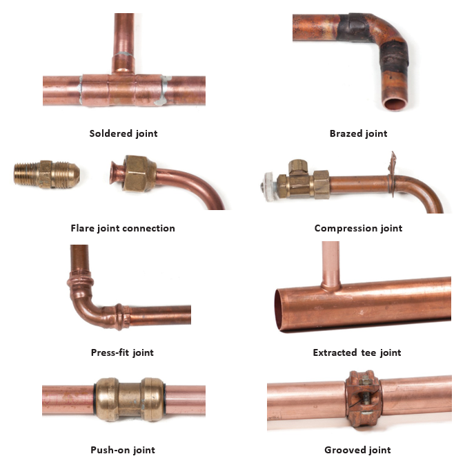
Soldering and Brazing Copper Jointing
The ability to make complete soldered or brazed jointing in copper tubing systems is essential for the tradesperson.
Soldering and brazing jointing is used in the following:
- Potable water systems (residential, commercial and industrial)
- Refrigeration tubing (silver brazing only; no soft soldering)
- Extracted tee joints in fire sprinkler systems
- Drainage, waste, and venting (DWV) systems
- Medical gas systems (brazing only; no soft soldering)
Soldering and Brazing Definitions
capillary action: The action by which liquid solder is drawn into the annular space between the inside fitting wall and the tubing outside wall due to attraction between the copper and the liquid solder molecules. This attraction is a result of the forces of adhesion, cohesion, and surface tension.
Capillary action is most effective when the space between surfaces to be joined is between 0.05 mm and 0.013 mm (0.002 in and 0.005 in). A certain amount of looseness of fit can be tolerated, but too loose a fit can cause difficulties with larger size fittings.
Solder joints depend on capillary action to draw free-flowing molten solder into the narrow clearance between the fitting and the tube. This occurs regardless of whether the solder flow is upward, downward, or horizontal.
soft soldering: Soldering at temperatures below 450°C (840°F).
hard soldering (brazing): Brazing at temperatures above 450°C (840°F).
solidus: The temperature at which 100% of the alloy is in a solid, crystalline form but starts to melt when additional heat is applied. Soldering begins upon reaching the solidus.
liquidus: The temperature at which 100% of the alloy is in a fluid, non-crystalline form. The liquidus temperature is the minimum temperature at which soldering or brazing will take place.
plastic range: The temperature range between the solidus and liquidus, where some portion of the alloy is solid but the majority is liquid. Also called the melting (pasty) range. It may be of importance when selecting a filler metal. It indicates the width of the working range for the filler metal and the speed with which the filler metal will become fully solid after brazing. Filler metals with narrow ranges, with or without silver, solidify more quickly and therefore require careful application of heat.
eutectic: A mixture having the lowest liquefaction point possible with a tin/lead mix. Alloys are eutectic when the solidus and liquidus are the same.
Soldering and Brazing Abbreviations
- Sn: tin
- Pb: lead
- Ag: silver
- Ni: nickel
- Cu: copper
- Sb: antimony
- Cd: cadmium
- Zn: zinc
Soldering and Brazing Materials
The following describes soldering and brazing materials.
Soft-Solder Filler Metals
Soft-solder filler metals belong to a group of filler metals with melting temperatures below 427°C (800°F). They are available in 1-pound spools in diameters of [latex]\frac{3}{64} \text{"}[/latex], [latex]\frac{1}{16} \text{"}[/latex], [latex]\frac{3}{32} \text{"}[/latex] and [latex]\frac{1}{8} \text{"}[/latex]. Other diameters and spool sizes are available on request.
Tin/Lead 50/50, 40/60, 60/40 Soft Solders
With some exceptions, the tin/lead solders can be used to solder copper and most copper alloys, lead, nickel alloys, and steel.
Tin/lead solders are not recommended in the cooling industry for joints subject to high stress or vibration due to their lack of sufficient elongation properties. It is illegal to use lead alloys in connection with potable water systems. (Refer to lead-free solder information.) These solders (40/60, 60/40, 50/50 – numbers referring to the percentage mix of metals) are available with rosin or acid cores.
Tin/Antimony 95/5
Tin/antimony 95/5 lead-free solder is useful for applications where moderately elevated temperatures are present. With higher electrical conductivity and high fluidity, 95/5 is recommended for lead-free installation of small-diameter, tight-fitting connections. Tin/ antimony solders are not recommended for use on brass.
Lead-free Solders
Lead-free solders were developed to conform to regulations banning the use of solders containing over 0.2% lead in potable water systems. These solders may contain some or all of the following metals: specific amounts of silver (Ag), antimony (Sb), copper (Cu), nickel (Ni) and/or tin (Sn). The strength of a lead-free solder joint normally exceeds the pressure at which copper tubing will burst.
Silver Brazing Filler Metal (Hard Soldering)
There are two general categories of silver brazing alloys:
- BAg—containing varying amounts of mainly silver and copper, with lesser amounts of other elements
- BCuP—similar to BAg, but with added phosphorus that acts as a flux
Selecting Solders or Brazing Alloys
The choice between soldering or brazing depends on operating conditions. Solder joints are generally used where the service temperature does not exceed 121°C (250°F), while brazed joints are used where greater tensile strength is required to resist vibration, pressure, or temperature cycling, or where system temperatures reach as high as 177°C (350°F).
Tube and Fittings Made for Soldering and Brazing
Copper tube and solder-type pressure fittings are accurately manufactured for compatibility. The tolerances permitted for each ensure the capillary space remains within the limits required for a strong enough joint.
Brazing Silver Copper Filler Alloys (BAg)
B (Brazing) and Ag (Silver) Element 47
These alloys are usually available in diameters of [latex]\frac{1}{32} \text{"}[/latex], [latex]\frac{3}{64} \text{"}[/latex], [latex]\frac{1}{16} \text{"}[/latex], [latex]\frac{3}{32} \text{"}[/latex] and [latex]\frac{1}{8} \text{"}[/latex] as wire, bare rod, or flux-coated rod, in straight lengths, coils, strips, rings, and other forms.
Sil-56
This high silver content (56%) alloy makes first-quality brazes. It is free-flowing with unequalled capillary attraction and deep penetration. Ductility is high, and corrosion resistance is suitable for most applications, except strong chemical environments. Sil-56 offers the highest elongation of silver brazing alloys, and is suitable for use in the food-processing industry. The silver colour is an excellent match for stainless steel and silverware applications.
Sil-45
This is an excellent general-purpose non-toxic brazing alloy. It has good ductility and capillary flow, and is often specified for government use. Its colour ranges from silver to light yellow, similar to polished brass.
Sil-25
This is a lower-cost brazing filler metal with good flow properties at relatively low brazing temperatures.
Brazing Copper Phosphorous Alloys (BCuP)
Phosphorous-copper and silver-phosphorous-copper alloys are used to braze copper-to-copper and copper-to-brass joints. The phosphorus content in these alloys makes them self-fluxing on copper. When brazing brass or copper to brass, use brazing flux. These alloys are not recommended for brazing steel or other ferrous metals.
Typical examples and usage of BCuP include medical gas systems, refrigeration systems, and other systems where flux is not permitted into the system. Available in stick form approximately 610 mm (24 in) long.
Fluxes
Soldering fluxes are classified as corrosive, intermediate, or non-corrosive. The selection depends on the metals being joined, the melting range of the solder, and whether residues will be removed after soldering.
Fluxes are either petroleum-based or water-based. Soft-solder joints require a flux to be applied to the metal surfaces prior to heating.
The purpose of a flux is to:
- Remove mild oxides
- Prevent oxides from forming (oxidation) while heating
- Wet the metal to permit the solder to flow smoothly over the surfaces and aid in capillary action
Different fluxes perform these duties differently at different temperatures. Therefore, the choice of flux depends on the metal being used and the temperature of the flow point of the solder.
Petroleum-Based Soft-Soldering Paste Flux
Petroleum-based paste fluxes are made of organic chlorides, zinc, bromides, fluorides, and ammonium chlorides mixed in a petroleum grease base. They are slightly corrosive, which helps clean the surface during soldering. Therefore, you must limit the amount of flux entering the joint and thoroughly clean the exterior after soldering to avoid visible discoloration and a poor, “shabby” appearance.
Water-Based Soft-Soldering Paste Flux
Water-based fluxes are a newer development. Experimenting with these new fluxes on the job may require changes to work practices. Many of these new fluxes are more sensitive to heat within the temperature ranges typically used for petroleum-based fluxes. Water-based fluxes may burn away, leaving residue and oxidation that can result in leaks once the system is activated (in service). Some begin reacting immediately upon application and do not allow for delays between fluxing and soldering. They contain chlorides and have an active soldering temperature range of 93 to 315°C (200 to 600°F).
Water-Based Brazing Fluxes
White brazing paste flux is good for use with silver-brazing most ferrous and non-ferrous metals, except aluminum, magnesium, and titanium. Recommended filler metals for use with white brazing flux include those in the BAg and BCuP classifications. White brazing paste flux contains water, boric acid, and potassium fluorides, and has an active temperature range of 566 to 871°C (1050 to 1600°F).
The shelf life of these types of fluxes is approximately one year from the time of manufacture.
Solder Joints and Brazed Joints
Methods of forming joints include soldering, brazing, and electric resistance soldering.
- Soldered joints, using capillary fittings, are used in plumbing for water lines and sanitary drainage.
- Brazed joints, using capillary fittings, are used where greater joint strength is required or where service temperatures may reach 177°C (350°F).
- Electric resistance soldering can be used for most soldering applications and is especially helpful when you need to bring the intended joint to temperature rapidly to avoid thermal damage to surrounding components.
Soldering and brazing can be defined as a group of joining processes that join materials together by heating them to a required soldering or brazing temperature and using a filler metal (solder).
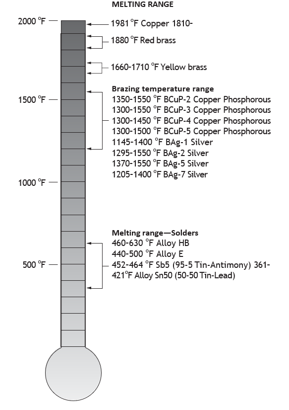
Solder generally has a liquidus temperature not exceeding 450°C (840°F) and below the solidus of the base metals. In actual practice, most soldering is done at temperatures from about 177 to 315°C (350 to 600°F). Brazing temperatures range from approximately 566 to 871°C (1050 to 1600°F).
Soldering and Brazing Specifications
Selection of Soldering Filler Metal
The selection of a solder depends primarily on the pressure and temperature at which the system will operate. Consideration should also be given to stresses on joints caused by thermal expansion and contraction. However, this may not be necessary when a tube length is short or when an expansion loop is used in a long tube run. In such cases, the stresses caused by a temperature change are usually insignificant.
When joining copper tube to soldered valves, follow the manufacturer’s instructions. The valve should be partially open before applying heat, and heat should be applied primarily to the tube. Commercially available heat-sink materials can also be used to protect temperature-sensitive components during the joining operation.
Copper tube and solder-type fittings are accurately manufactured to work together. The tolerances permitted for each ensure the capillary space will be within the limits necessary for a joint of satisfactory strength. Soldered joints rely on capillary action to draw free-flowing molten solder into the gap between the fitting and the tube. Flux acts as a wetting agent and, when properly applied, permits uniform spreading of the molten solder over the surfaces to be joined.
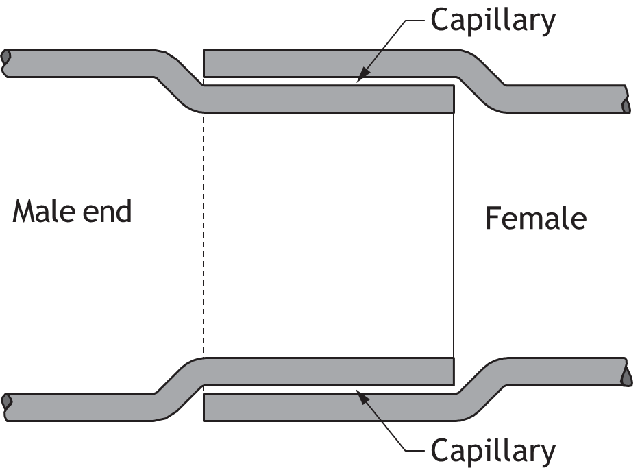
The 50/50 tin-lead solder is suitable for moderate pressures and temperatures. For higher pressures or where greater joint strength is required, 95/5 tin-antimony solder can be used. For continuous operation at temperatures exceeding 121°C (250°F) or where the highest joint strength is required, brazing filler metals should be used.
Solder alloys that meet ASTM B32, Standard Specification for Solder Metal (a standard that defines requirements for solder materials), can be used to join copper tube and fittings in potable water systems. Solders containing lead at concentrations of greater than 0.2% are banned for potable water systems. Some jurisdictions may allow the use of 50/50 tin-lead solder in some HVAC, drainage, and other piping system applications.
Always refer to manufacturers’ documentation and applicable code regulations.
Soldering and Brazing Procedures
To consistently make satisfactory joints, the following sequence of joint preparation and operations, based on ASTM Standard Practice B 828, should be followed.
First Preparation Procedures: Measuring and Cutting
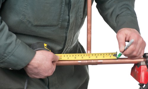
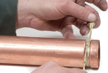
Soldering and brazing to produce a solid, leak-proof joint begin with accurately measuring the length of each tube segment (Figure 3). Inaccurate measurements can compromise joint quality. If the tube is too short, it will not fully enter the fitting cup, and a proper joint cannot be made. If the tube segment is too long, system strain may be introduced, which can affect service life.
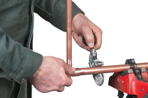
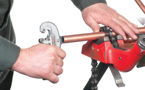
Cut the tube to the measured length. There are a number of different methods to produce a satisfactory squared end. The tube can be cut with a disk-type tube cutter, a hacksaw, an abrasive wheel, or a stationary or portable bandsaw. Care must be taken that the tube is not deformed during cutting. Regardless of the method used, the cut must be square to the run of the tube (the straight direction or alignment of the pipe) so that it seats properly in the fitting cup.
Reaming
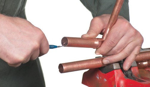
Ream all cut tube ends to the full inside diameter of the tube to remove burrs created during cutting. If this rough inside edge is not removed by reaming, erosion-corrosion may occur due to local turbulence and increased local flow velocity in the tube. A properly reamed piece of tube provides a smooth internal surface for better flow.
Remove any burrs on the outside of the tube ends that were created during the cutting operation, to ensure proper insertion of the tube into the fitting cup.
Tools used to ream tube ends include the reaming blade on the tube cutter, half-round or round files, and suitable de-burring tools. With soft tubing, care must be taken to avoid deforming the tube end by applying too much pressure.
Soft temper tube, if deformed, can be brought back to roundness with a sizing tool. This tool consists of a plug and sizing ring.
Cleaning
The removal of all oxides and surface soil and contaminants from the tube ends and fitting cups is crucial for proper solder flow into the joint. If not removed, they can interfere with capillary action, lessening the strength of the joint and causing failure.
Lightly abrade (clean) the tube ends using sand cloth or nylon abrasive pads to a distance slightly greater than the depth of the fitting cup.
Clean the fitting cups using abrasive cloth, abrasive pads, or a properly sized fitting brush.
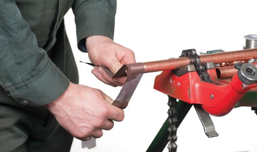
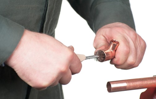
Do not touch the cleaned surface with bare hands or oily gloves. Skin oils, lubricating oils, and grease can impair the soldering process.
Copper is a relatively soft metal. If too much material is removed from the tube end or fitting cup, a loose fit may result, leading to a poor joint. The capillary space between tube and fitting is approximately 0.1 mm (0.004 in). This spacing is critical for the solder metal to flow into the gap and form a strong joint.
Applying Flux
Use care in applying flux. Careless workmanship can cause problems long after the system has been installed. First, apply a thin, even coating of flux to the tube using a brush, then apply a smaller amount to the inside of the fitting hub. Flux the fitting as soon as possible after cleaning. If you apply too much flux inside the hub, the excess will get pushed into the pipe. Excessive flux can leave residue that may cause corrosion. In extreme cases, this corrosion could perforate the wall of the tube, fitting, or both.
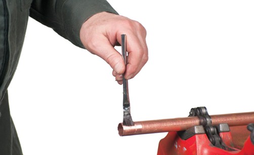
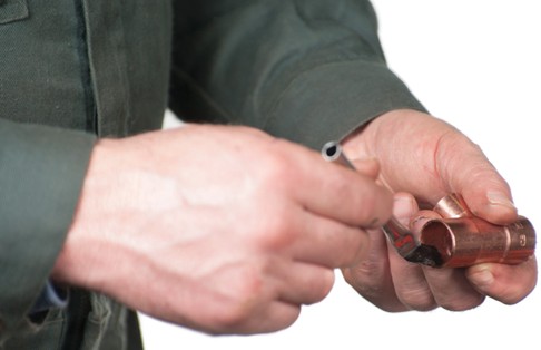
Assembly and Support
Insert the tube end into the fitting cup, making sure that the tube is seated against the base of the fitting. A slight twisting motion helps distribute the flux evenly. Remove excess flux from the exterior of the joint with a clean cotton rag.
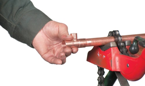
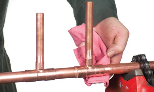
Support the tube and fitting assembly to maintain a uniform capillary space around the entire circumference of the joint. Uniformity of capillary space will ensure good capillary flow of the molten-solder metal. Excessive joint clearance may lead to solder metal cracking under conditions of stress or vibration. The joint is now ready for soldering.
Joints should be soldered the same day they are prepared and not left overnight.
Heating
Begin heating with the flame at right angles to the tube (Figure 14). The copper tube conducts the initial heat into the fitting cup to produce even distribution of heat in the joint area. The extent of this preheating depends upon the size of the joint. Preheating of the assembly should include the entire circumference of the tube in order to bring the entire assembly up to a suitable preheat condition. For horizontal joints, avoid directly preheating the top of the joint to avoid burning the soldering flux. The natural tendency for heat to rise will ensure adequate preheat of the top of the assembly. Practice and experience will indicate the amount of heat and the time needed.
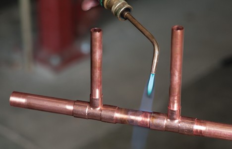
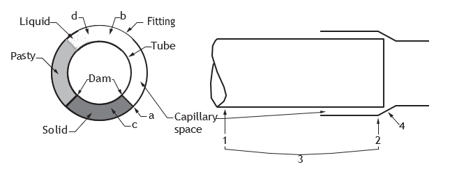
Next, move the flame onto the fitting cup (Figure 16, position 2). Sweep the flame alternately between the fitting cup and the tube approximately a distance equal to the depth of the fitting cup (Figure 15, right, position 3). Again, preheat the circumference of the assembly as described above, with the torch at the base of the fitting cup (Figure 15, right, position 4). Touch the solder to the joint. If the solder does not melt, remove it and continue heating.
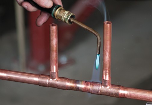

Applying Solder
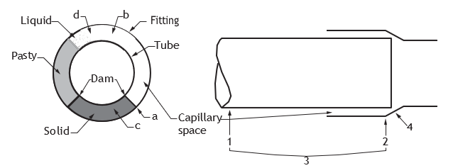
Continue heating while touching the solder to the joint. When the solder melts, apply heat to the base of the fitting cup to aid capillary action in drawing the molten solder into the cup toward the heat source. For joints in the horizontal position, start applying the solder metal slightly off-centre at the bottom of the joint (Figure 15, left, position a, and Figure 17). When the solder begins to melt from the heat of the tube and fitting, push the solder straight into the joint while keeping the torch at the base of the fitting and slightly ahead of the point of application of the solder. Continue this technique across the bottom of the fitting and up one side to the top of the fitting (Figure 15, left, position b).
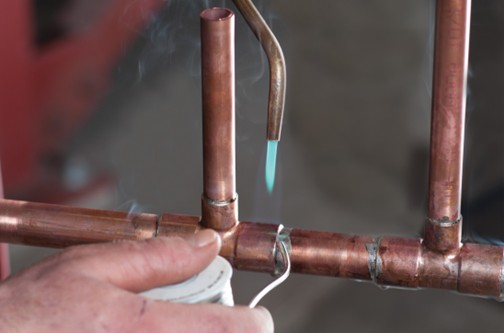
Return to the point of beginning, overlapping slightly (Figure 15, left, position c), and proceed up the uncompleted side to the top, again overlapping slightly (position d). While soldering, small drops may appear behind the point of solder application. These indicate that the joint is full to that point and will take no more solder. During this process, solder transitions through solid, pasty, and liquid states.
The now-solidified solder at the bottom of the joint has created an effective dam or barrier that will prevent the molten solder from running out of the joint as the side and top of the joint are being filled.
For joints in the vertical position, make a similar sequence of overlapping passes, starting wherever is convenient.
Cooling and Cleaning
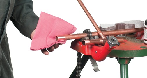
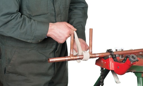
Allow the completed joint to cool naturally. Shock cooling with water may stress the joint. When cool, clean off any remaining flux residue with a wet rag (Figure 18). Whenever possible, based on end use, flush the system to remove excess or residual flux and debris.
Testing
Test all completed assemblies for joint integrity. Follow the testing procedure prescribed by applicable codes governing the intended service.
Visual Examination
The finished joint shall be visually inspected. The following conditions shall be considered unacceptable:
- Excess solder drips on the outside of the tube and/or fitting
- Cracks in the tube or fitting
- Cracks in the solder filler metal
Brazed Joints
Brazing Filler Metal Alloys
Brazing filler metals are used in plumbing, HVAC, refrigeration, and fire sprinkler systems. For joining copper tube, any of these filler metals will provide the necessary strength when used with standard solder-type fittings or commercially available short-cup brazing fittings. Brazing filler metals are sometimes referred to as “hard solders” or “silver solders.” These confusing terms should be avoided.
There are two classes of brazing filler metals suitable for joining copper tube:
- BCuP series alloys containing phosphorus: brazing (B), copper (Cu) phosphorous (P)
- BAg series alloys containing a high silver content: brazing (B), silver (Ag)
The two classes of brazing metals differ in their melting, fluxing, and flowing characteristics, and this should be considered when you are selecting a filler metal.
Each class of filler metal comes in variations for specific uses:
- BCuP-2: used for close tolerances
- BCuP-3, BCuP-4and BCuP-5: used where close tolerances cannot be held
- BAg-1, BAg-5 and BAg-7: used when the specific characteristics of the BAg alloy are required
Brazing alloy key characteristics:
- BAg filler metals are used for joining dissimilar metals.
- The BCuP series filler metals are less expensive than the BAg series.
- BCuP alloys are better suited for general piping applications.
- The strength of the brazed joint will meet or exceed that of the tube and fitting being joined.
- Depending on the composition of either BAg or BCuP alloys, they melt at temperatures between 590 and 815°C (1100 to 1500°F).
- Brazing filler metals can form strong, leak-tight brazed connections for copper tube.
- The temperature at which a filler metal starts to melt on heating is the solidus temperature; the liquidus temperature is the higher temperature at which the filler metal is completely melted. The liquidus temperature is the minimum temperature at which brazing will take place.
- The difference between solidus and liquidus is the melting (pasty) range and may be of importance when selecting a filler metal. It indicates the width of the working range for the filler metal and the speed with which the filler metal will become fully solid after brazing. Filler metals with narrow ranges, with or without silver, solidify more quickly and therefore require careful application of heat.
For details about brazing filler metal composition, use the manufacturers’ documentation.
Strength of Brazed Joint
The strength of a brazed copper tube joint does not vary much with the different filler metals. The joint strength depends mainly on maintaining the proper clearance between the outside of the tube and the cup of the fitting.
Brazing Flux
The fluxes used for brazing copper joints are different in composition from soldering fluxes. The two types must not be used interchangeably.
Unlike soldering fluxes, brazing fluxes are water-based. However, brazing fluxes perform the same functions as soldering fluxes:
- Dissolve and remove residual oxides from the metal surface
- Protect the metal from re-oxidation during heating
- Promote wetting of the surfaces to be joined by the brazing filler metal
Brazing fluxes also provide an indication of temperature (Figure 20).
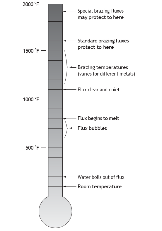
The flux can be used as a guide as to how long to heat the tube.
By observing the flux reaction during soldering or brazing, you can judge the temperature and avoid overheating. Excessive oxidation will be minimized, and the appearance of the joint will be greatly improved.
For information about flux requirements based on tube, filler metal, and fitting type, refer to manufacturer documentation.
Brazing Procedures
The procedures for measuring, cutting, de-burring, cleaning, fluxing, and assembly are the same as for soldering. The following brazing procedures start once heat is applied to the joint being brazed.
When brazing larger diameters, a B tank will work with a larger tip, or multiple B tanks could be used. However, an oxy-acetylene fuel torch with a neutral to slightly carburizing flame is preferred.
Apply Heat
Heat the tube first, beginning about 2.5 cm (1 in) from the edge of the fitting and sweeping the flame around the tube in short strokes at right angles to the axis of the tube (Figure 21, right, position 1).
It is very important that the flame remain in motion and not stay in one spot long enough to damage the tube.
Switch the flame to the fitting at the base of the cup (Figure 21, right, position 2). Heat uniformly, sweeping the flame from the fitting to the tube until the flux on the fitting becomes quiet (stops bubbling and becomes smooth). Avoid excessive heating of cast fittings, as this may cause cracking.
When the flux appears liquid and transparent, start sweeping the flame back and forth along the axis of the joint to maintain heat on the parts to be joined, especially toward the base of the cup of the fitting (Figure 21, right, position 3). The flame must be kept moving to avoid melting the tube or fitting.
For tube sizes 2.5 cm (1 in) or larger, it may be difficult to bring the whole joint up to temperature at one time. It frequently will be found desirable to use an oxy-fuel, multiple-orifice heating tip to maintain a more uniform temperature over a large area. A mild preheating of the entire fitting is recommended for larger sizes, and the use of a second torch to retain a uniform preheating of the entire fitting assembly may be necessary in larger diameters. Heating can then proceed as outlined in the steps above.
Applying the Brazing Filler Metal
Apply the brazing filler metal at a point where the tube enters the fitting socket. When the correct temperature is reached, the filler metal will flow readily into the space between the tube and fitting socket, drawn in by the natural force of capillary action.
Keep the flame away from the filler metal itself as it is fed into the joint. The temperature of the tube and fitting at the joint should be hot enough to melt the filler metal.
Keep both the fitting and tube heated by moving the flame back and forth from one to the other as the filler metal is drawn into the joint. When the joint is properly made, filler metal will be drawn into the fitting socket by capillary action, and a continuous fillet of filler metal will be visible completely around the joint. To aid in the development of this fillet during brazing, the flame should be kept slightly ahead of the point of filler metal application.
Horizontal and Vertical Joints
When brazing horizontal joints, it is preferable to first apply the filler metal slightly off-centre at the bottom of the joint, proceeding across the bottom of the joint, and continuing up the side to the top of the joint. Return to the beginning point, overlapping slightly, and proceed up the uncompleted side to the top, again, overlapping slightly. This procedure is identical to that used for soldering.
Also, similar to the soldering process, make sure the operations overlap. On vertical joints, it is immaterial where the start is made. If the opening of the socket is pointing down, avoid overheating the tube, as this may cause the brazing filler metal to run down the outside of the tube.
Removing Residue
After the brazed joint has cooled, remove flux residue using a clean cloth, brush, or swab with warm water. Remove all flux residue to avoid the risk of the hardened flux temporarily retaining pressure and masking an imperfectly brazed joint. Wrought fittings cool faster than cast fittings, but all fittings should be allowed to cool naturally before wetting and cleaning.
Techniques for troubleshooting brazing include:
- If the filler metal fails to flow or has a tendency to ball up or bead, it indicates oxidation on the metal surfaces or insufficient heat on the parts to be joined.
- If the tube or fitting starts to oxidize during heating, insufficient flux has been used.
- If the filler metal does not enter the joint and tends to flow over the outside of either member of the joint, it indicates one part is overheated or the other underheated.
Testing
Test all completed assemblies for joint integrity. Follow the testing procedure prescribed by applicable codes governing the intended service.
Purging
Some installations (such as medical gas, high-purity gas, and ACR systems), require the use of an inert gas during the brazing process. The purge gas (usually nitrogen) displaces oxygen from the interior of the pipe system while it is being subjected to the high temperatures of brazing and therefore eliminates the possibility of oxide formation (oxidation) on the interior tube surface during heating.
Purge gas flow rates and methods of application should be included in the Brazing Procedure Specifications of these applications.
Visual Examination
The finished joint should be visually inspected. The following conditions shall be considered unacceptable:
- Excess filler metal on the outside of the tube and/or fitting
- Cracks in the tube or fitting
- Cracks in the filler metal
Copper Swaging
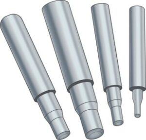
The Canadian Oxford Dictionary (2004) defines the term “swage” as “A tool, die, or stamp for bending and shaping wrought iron, etc., by hammering or pressure.” A pipe swage for copper is a tool that expands the end of an annealed piece of copper tube to form a coupling.
One type of swaging tool uses a hand-held steel pin or mandrel that is driven into the tube end by repeated hammer blows, thereby expanding the inside diameter of the tube. Each size of tube requires a different size of swage.
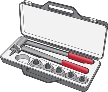
Another type of swage uses handles that are pumped to expand a die. The die is placed into the pipe end and, when the handles are opened and closed repeatedly, the die expands and forms the coupling. Like the hand swage, each pipe size requires a different die head.
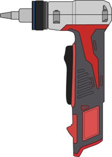
This variety of swage is more commonly known as a tube expander, and can also be found using an electric motor to power the swaging movement.
To be an acceptable joint, pipe swage manufacturers usually specify that the newly formed expanded connection should be brazed rather than soldered.
Extracted Tee Joints
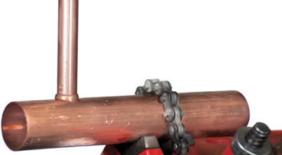
Extracted tee joints are a tested and effective method for joining copper tubes. In this method, the tool forms a raised collar on the pipe to which another tube is brazed. Soldering is not permitted, because the joint would not be strong enough.
Power or hand tools quickly form an extracted tee connection in a run of copper tube, reducing the number of soldered or brazed joints. The process is faster than individual tees piped together (because there are fewer joints) and can reduce installation costs. This method may be used for general plumbing, HVAC, refrigeration, fire sprinkler, and service projects.
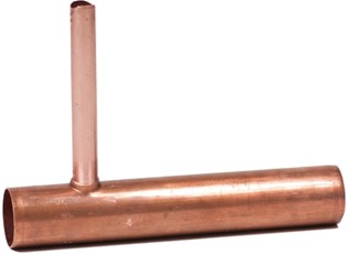
Typical Code Regulations
Extracted tees can be formed from Type K and Type L copper used in water distribution systems, provided the following requirements are met:
- A tool specifically designed to form the joint is used.
- The branch line size is at least one size smaller than the tube in which the tee is formed (the main tube).
- The end of the branch incorporates a means to prevent the branch from penetrating into the run of the tube and obstructing the flow.
- The joint is brazed using filler metal with a melting temperature of at least 540°C (1004°F).
Figure 26 shows a tube end preparation tool that forms the end of a branch pipe to match the inner curve of the tube. The tool simultaneously presses two dimples in the end of the branch tube. One acts as a depth stop, and the other is used to inspect branch alignment after brazing.
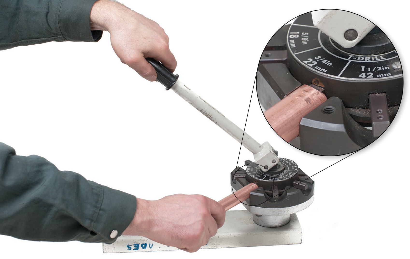
On larger tube sizes and/or heavier wall thicknesses, the area for forming the tee outlet must be annealed before preparing an extracted tee joint. Refer to manufacturer instructions when working with these sizes.
Installation Steps
The following procedure is typical for forming and brazing 12.5 to 31.75 mm ([latex]\frac{1}{2}[/latex] to 1[latex]\frac{1}{4}[/latex] in) outlets using power-operated equipment. Although there are specific steps to follow, the tee-forming and brazing process takes little time and is quickly repeatable. Follow the manufacturer’s operating instructions for all tube sizes.
- Select and adjust the drill head and forming pins according to the manufacturer’s instructions. The drill bit and pins are quite sharp, so be careful when handling them.
- Insert the drill head into the chuck (Figure 27) and extend the forming pins (Figure 28).
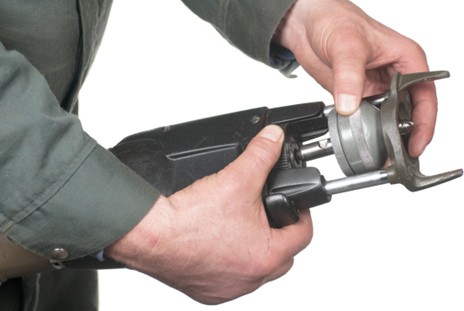
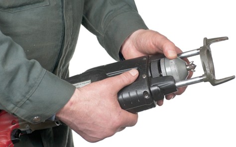
- Lubricate the drill head and forming pins (Figure 29).
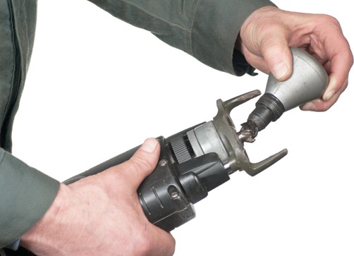
Figure 29 Lubricate drill head (BC Industry Training Authority, 2019). CC BY-NC-SA 4.0
- Pull out the support legs (Figure 30).
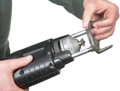
- Press in the conical cover and rotate counter-clockwise to retract the forming pins (Figure 31).
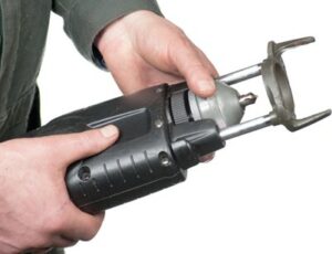
Figure 31 Retract the pins (BC Industry Training Authority, 2019). CC BY-NC-SA 4.0 - Place the tube support firmly at the point where the tee is to be formed on the tube. Then twist the machine counter-clockwise using the handle to centre the drill head on the tube. The support legs will centre and stabilize the drill while absorbing rotational torque (Figure 32).
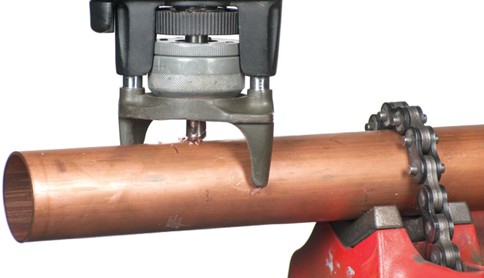
- Start the tool by squeezing the trigger and drill until the bit has fully penetrated into the tube. Then release the trigger to stop the drill. Do not extend the forming pins while the motor is running.
- Extend the forming pins on the drill head by pressing the cover toward the tool and rotating it counter-clockwise until the head locks in the tee-forming position (Figure 33).
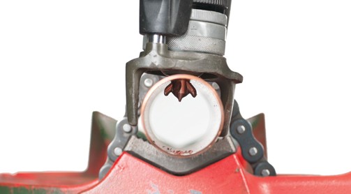
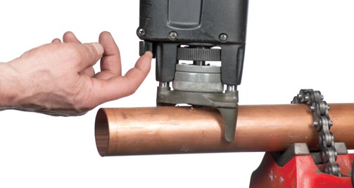
- Turn the speed selector control to the slowest position (typical) and engage the feed mechanism. You may need to rotate the motor by giving a nudge on the trigger to engage it.
- Squeeze the trigger to start forming the outlet and continue until the drill head exits completely out of the tube (Figure 35). Maintain a slight downward pressure on the drill to ensure a firm contact with the tube. The rotation of the forming pins causes a backflow and thickening of the metal around the lower circumference of the outlet. It is important to release the drill trigger as soon as the drill head clears the rim of the outlet. Note: Removing the drill head from the tube before it emerges will result in an oval or imperfect outlet.
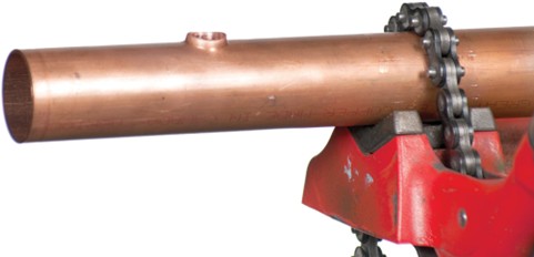
- Select the appropriate branch-size die on the tube-end notcher to notch and dimple the sides of the branch tube end. Proper notching and dimpling must be performed to meet code requirements and to ensure that the branch does not protrude into the tube and obstruct flow.
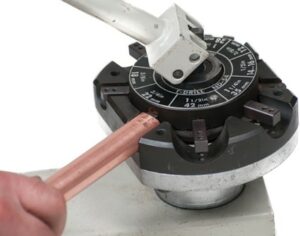
- Ream or de-burr the branch tube end.
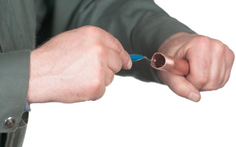
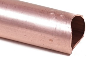
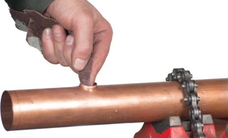
- Remove any excess lubricant from inside the outlet and use a sand cloth to clean the inside of the outlet rim.
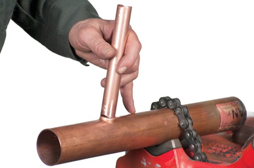
- Insert the branch tube into the outlet up to the first dimple and align the dimples with the run of the tube.
- Align the joint for brazing and complete the brazing process using the specified filler metal and following the normal joint procedures.
Testing the Extracted Tee Joint System
All drilling residue and debris must be flushed out before the system is placed in service.
Final pressure testing of the completed piping system is accomplished by using pressurized air or water as required by local codes or project specifications. Test pressures should never exceed the maximum operating pressure specified by the manufacturer of the fitting system.
Push-Connect Joints
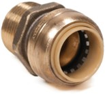
Push-connect joints use an integral elastomeric gasket or seal (such as EPDM) and a stainless-steel grab ring to produce a strong, leak-free joint connection. This push-on method of joining of copper and copper alloy tube is fast and may be economical in specific applications.
There are two common types of push-connect fitting: removable and permanent. Both create strong, permanent joints. However, one allows easy removal after installation (Figure 42) to permit equipment service, while the second type cannot be easily removed once the fitting is installed.
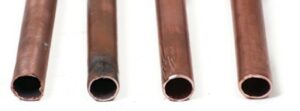
Examine the tube to ensure that it has no dents, deep scratches, dirt, oils, paint, grease, or other surface imperfections.
Push-On Fitting Installation Procedure
- Measure and cut the tube square, perpendicular to the run of tube, using an appropriate tubing cutter.
- Remove burrs from the inside diameter (ID) and the outside diameter (OD) of the cut tube end by reaming the ID and chamfering the OD using the appropriate tools.
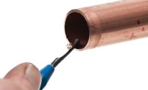
- The cut tube end must be chamfered to reduce the possibility of gasket damage when the tube is being inserted. Cleaning the chamfered tube end with emery paper, abrasive nylon cloth, or plumber’s cloth will ensure that there are no sharp edges or nicks that might damage the sealing gasket when the tube is inserted into the fitting.
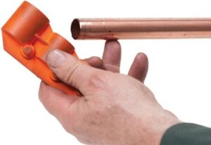
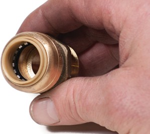
- Examine the fitting to ensure that the sealing gasket and gripper ring are properly positioned and not damaged.
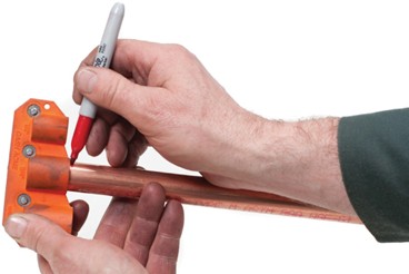
- Mark the depth of insertion on the tube before inserting it into the fitting to ensure that it will socket to the back of the fitting cup.
Note: Lubrication of the tube end may or may not be required. Follow the manufacturer’s installation recommendations related to pre-lubrication of the tube end.
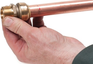
- Align the tube so that it is straight and in line with the fitting. Using a firm pushing and twisting motion, insert the tube into the fitting and push the tube and fitting together until the tube is seated at the back of the fitting cup, as evidenced by the pre-marked tube insertion depth line.
- Test the completed piping system using pressurized air or water as required by local codes or project specifications. Test pressures should never exceed the maximum operating pressure specified by the manufacturer of the fitting system. Refer to manufacturers’ instructions.
Press-Fit Joints
The press-connect joining method and associated fittings and tools were introduced in North America in the late 1990s. Also known as press-fit, this method has been used successfully in Europe since it was patented there in the late 1950s.
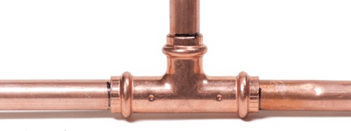
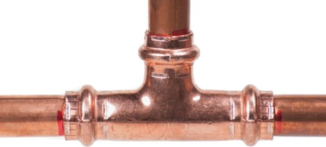
Press-fit joints rely on the sealing capability of a special fitting that contains an elastomeric gasket or seal (such as EPDM) (Figure 49).
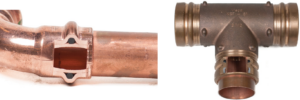
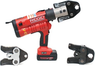
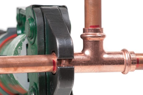
The joint is formed using an approved pressing tool and jaws (Figure 50). Typical ranges of pressure-temperature ratings for these no-flame joints can be found in the manufacturers’ documentation.
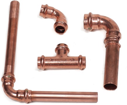
Several manufacturers offer full product lines of press-connect fittings, valves, and specialty items (Figure 51). Tubing is available with an integrally formed press-connect end.
Examine the tube to ensure there are no dents, deep scratches, dirt, oils, grease, or other surface imperfections.
Press-connect Fitting Installation Procedure
- Measure tubing accurately to ensure it sockets completely to the base of the fitting cup.
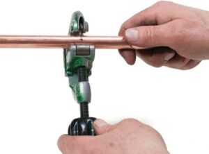
- Cut the tubing square, perpendicular to the run of tube, using an appropriate tube cutter.
- Deburr the tubing. Burrs must be removed from the ID and OD of the cut tube end.
- Chamfer the cut tube end to reduce the possibility of gasket damage when inserting the tube. Clean the chamfered tube end with emery paper, nylon abrasive cloth, or plumber’s cloth to ensure there are no sharp edges or nicks that might damage the sealing gasket when the tube is inserted into the fitting.
- Examine the fitting to be used to ensure the sealing gasket is properly positioned and is not damaged.
- Mark the depth of insertion on the tube before inserting the tube into the fitting.
- Select the proper size of the appropriate pressing jaw and insert it into the pressing tool.
- Ensure that the tube is completely inserted to the fitting stop (appropriate depth) and squared with the fitting before applying the pressing jaws onto the fitting.
- Place the pressing jaw over the bead on the fitting and ensure the tool and jaws are at a 90° angle (perpendicular) to the centreline of the tube.
- Depress the pressing tool trigger to begin the pressing cycle.
- When the pressing cycle is complete, release the pressing jaw and visually inspect the joint.
Testing the System Joints
Test the completed piping system using pressurized air or water. When the test pressure is relatively high, use hydro-pneumatic testing. The test pressures should never exceed the maximum operating pressure specified by the manufacturer of the fitting system. Check the documentation they provide and always follow manufacturer specifications and applicable codes.
Roll Groove Joints
Since 1925, the grooved-end piping method has been used reliably to join steel and iron pipe in HVAC, fire protection, process piping, and related applications.
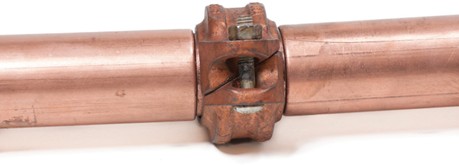
This method of mechanical joining is also available in a system for copper tube in sizes from 5 to 20 cm (2 to 8 in). Included are couplings, gaskets, and a myriad of fitting configurations. The system offers a practical alternative to soldering and brazing larger-diameter copper tube—and most importantly, it requires no heat or open flame.
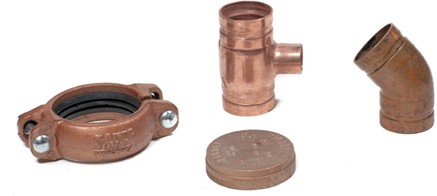
Copper roll groove joining takes advantage of copper’s excellent malleability and its increased strength when cold-worked. The joints rely on the sealing capability of a special clamping system that contains an EPDM gasket and a specially designed clamp. Several manufacturers offer roll groove tools, gaskets, clamps, and fittings (Figure 57).
Roll Groove Copper Tube Joining Procedures
Proper selection of the correct roll grooving tool and heads for each type of tube to be prepared is essential. Manufacturers’ recommendations must be followed to ensure safe, trouble-free tube preparation.
- Examine the tube to ensure there are no dents, deep scratches, dirt, oils, grease or other surface imperfections.
- Measure the tube length accurately.
- Cut the tube end square (perpendicular to the run of the tube).
- Remove burrs (de-burr) from the ID and the OD of the tube end by reaming the ID and chamfering the OD.
- Roll groove the tubing to the proper dimensions, as required by the fitting manufacturer.
- Examine the fittings, gaskets, and clamps to ensure the proper gasket is inserted into the clamp and the fitting end is not damaged.
- Inspect the clamping surfaces to ensure they are clean and free from construction debris.
- Lubricate the gasket according to the manufacturers’ recommendations.
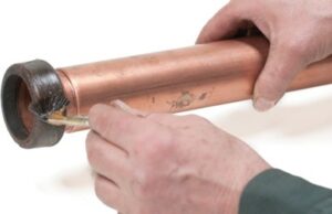
- Assemble the clamp and pipe, ensuring that the gasket and groove and sealing surfaces align and seal correctly.
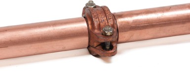
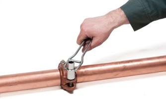
- Tighten the clamp evenly.
- Visually inspect the completed joint alignment, etc.
- Test the completed piping system using pressurized air or water. When the test pressure is relatively high, hydro-pneumatic testing may be used. Test pressures should never exceed the maximum operating pressure specified by the manufacturer of the fitting system. Test pressures are determined by the job specifications and regulations standards such as the plumbing code, fire sprinkler code, or other applicable codes.
Bending of Pipe and Tubing
Most pipe and tube can be bent. There are several benefits to bending, including:
- Reduced or eliminated unnecessary joints and connections, resulting in fewer leaks
- Greater flexibility of pipe when bends rather than fittings are used
- The ability to create offsets at angles not available with manufactured fittings
This basic bending information section focuses on tube bending only.
Tube bending is used in refrigeration and other piping systems, including, but not limited to, gas fitting applications, residential fuel oil systems, pneumatic control piping, and small-diameter water lines to plumbing fixtures.
When copper tube is properly bent, it will not collapse on the outside nor buckle the inside of the bend. Because copper is readily formed, expansion loops and other bends necessary in an assembly can be made quickly and efficiently. A well-constructed system of exposed tubing will also present a more professional appearance when bends are used instead of fittings.
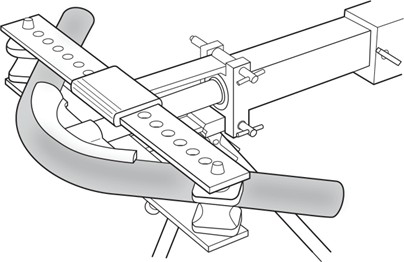
Both annealed and hard-drawn tube can be bent using the appropriate hand benders. Use the proper size of bender for each tube size. Refer to manufacturers’ guides for a list of each tool’s typical bend radii.
Aside from brittle pipe materials, such as cast and ductile iron, both ferrous and non-ferrous pipe can be bent using machines. Machine bending methods include draw bending, compression bending, roll bending, ram bending, and stretch bending. The use of dies and rolls helps prevent the pipe from distortion that could cause pipe failure or difficulty connecting to other pipes or fittings. Cold and hot bending, bend radius, bend angle, throat-of-bend, back-of-bend, bend arc, inner curvature, outer curvature, thinning, stretching and shortening are some of the terminology that will be used in pipe bending theory for steel pipe, which will be covered in detail in future levels of your apprenticeship training.
Plastic Fusion Welding Jointing Methods
Thermoplastic pipe is increasingly used in many industries, such as gas, water, and mining. The advantages over traditional materials (e.g., steel and cast iro) include lower cost, resistance to corrosion, lighter weight, and ease of joining. Ease of joining is only applicable if installation is done by qualified personnel following correct procedures and pipe and fitting tolerances.
The information, procedures, and equipment described here are generic and do not represent any specific manufacturer. Fusion welding of plastic pipe may require specific training and certification by a particular manufacturer to conform to the product they are providing.
Fusion welding is a type of welding that uses hot air or heating plates to fuse certain types of plastic piping. For example:
- Plain-end pipe: joined by butt fusion
- Hub-to-spigot pipe: joined by socket fusion
- Branch connections (tees): often formed by saddle fusion
Polyethylene piping can be heat welded by socket fusion.
Heat fusion welding of high-density polyethylene pipe (HDPE) employs specially designed heating elements along with appropriate forming blocks, cutting tools, and clamping devices to fusion weld the pipe joint.
The heating element heats the pipe and fitting components to a temperature at which the HDPE material begins to soften and melt. At a specified temperature, the heating element is removed, the opposing joint surfaces are brought together, and a specific force is held on the joint, forcing the two heated surfaces to mix and become one. As they cool, the joint forms a single continuous material with strength comparable to the original pipe.
General Safety Specific to Fusion Welding and Machines
Follow all safety requirements.
Before adjusting or attempting maintenance, disconnect the machine from the power source. The heater is hot and will burn clothing and skin. Keep the heater in its insulated heater stand or blanket when not in use and use care when heating the pipe.
Use only a clean, natural-fibre cloth (such as a cotton) to clean heater plates.
Basic Fusion Welding Equipment
The subtopics describe some basic fusion welding equipment to be familiar with.
Heating Irons
Specially shaped heating irons (also called heaters) are used to:
- Heat pipe ends for butt fusion
- Heat the inside of fittings and the outer surface of the end of a pipe for socket fusion
- Heat the exterior wall of a pipe and its mating surface on a fitting for saddle fusion
With all types of joining with heating irons, the heating iron is applied to the surface of the mating components until each surface melts but does not burn.
The length of time required to heat a joint is determined from the manufacturer’s specifications and used for heating the joints systematically.
When irons have seen a lot of use, the protective non-stick coating can be damaged. At some point, this will allow the melted plastic to stick and interfere with the actual joint. Replacement adapters would need to be purchased. Some irons have temperature gauge and temperature adjustment screws. Check the fitting manufacturer’s instructions for appropriate temperature settings.
Coated heater adapters are available for all fusion applications. Heater adapters are installed with stainless steel cap screws. Ensure that the heater adapters are seated on the heater body and that there is no foreign matter trapped between these surfaces. Do not over-tighten the bolts. The surface of the heater adapters are coated with an anti-stick coating. Only install heater adapters when the heater is cool. Check manufacturer’s tightening instructions.
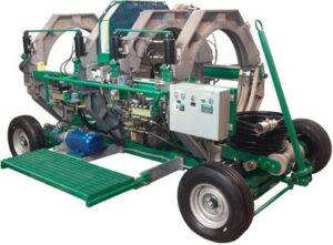
The following figure shows an example of a large-diameter poly pipe fusion machine.
Other Fusion Welding Equipment
Pyrometer
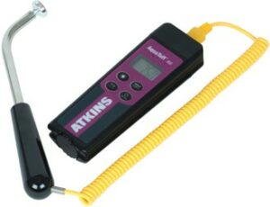
Incorrect heating temperature can result in poor fusion joints. Periodically check heater plate surface temperature with a properly calibrated pyrometer and make necessary adjustments. The thermometer on fusion heaters indicates internal temperature and should be used as a reference only.
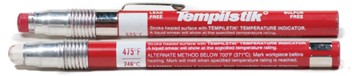
You can use a Tempilstik to check the heating element surface temperature. Simply apply the end of the stick to the surface of the heater. Never touch the stick to the surface being melted, as you could contaminate the joint.
Fusion-Welding Assembly
Figure 68 shows a small-diameter fusion assembly used for fusion-welding poly pipe.
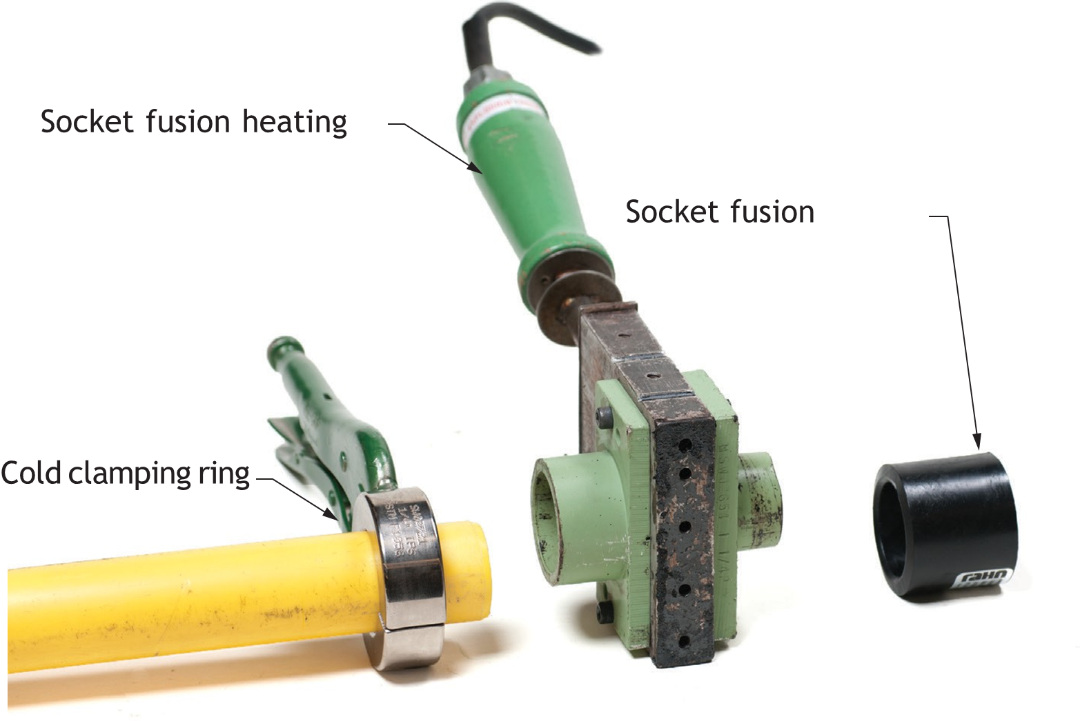
This assembly holds the pipe tight with built-in cold-clamping rings (A). The cold clamps are tightened around the pipe using a handle (C).
The system can be used for butt fusion or saddle connections. For pipe saddles, the chains wrap around the pipe and hook into the latches (B).
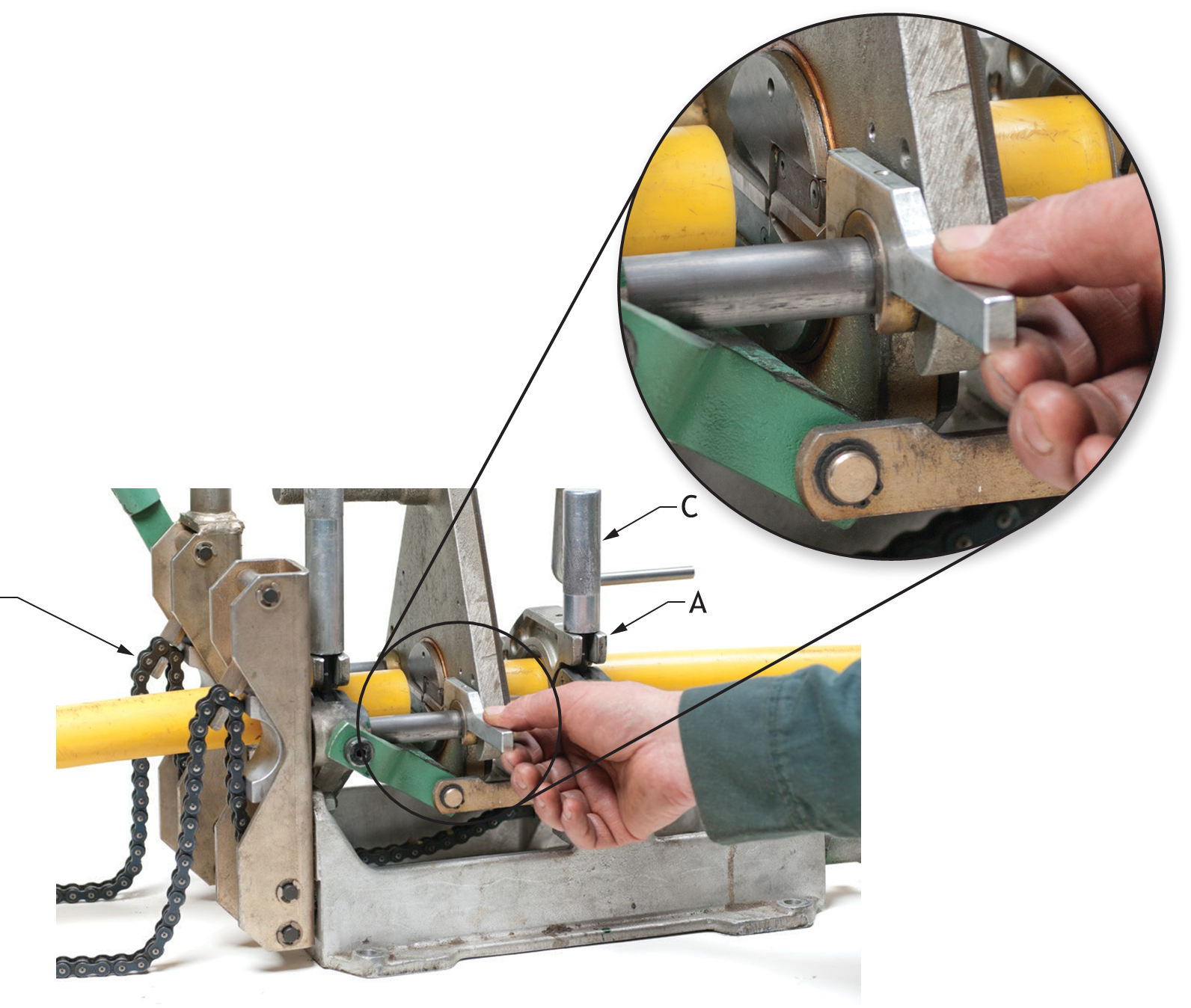
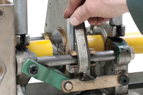
Figure 68 shows the pipe facer mounted on the fusion machine. The pipe ends have been lined up for a butt fusion weld. The facer/trimmer has been lowered into place to trim the ends of each pipe. The operator is holding the locking lever ready to swing it up to the locked position.
Pipe Facer
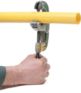
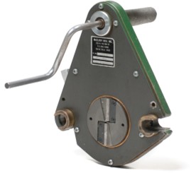
A pipe facer (trimmer) fits onto the fusion assembly and is used to trim the ends of the poly pipe square for butt fusion welding. Before using the facer, also known as a trimmer, make sure the pipe ends are aligned with each other by checking the outside diameters for perfect circumference alignment. The figures below show the facer being installed.
In Figure 71, the facer/trimmer locking lever has been swung up and locked into position. The facer is now ready to trim the ends of the pipe perfectly square and smooth. The cold-clamp handles have been tightened on both pipes on both sides of the facer/trimmer.
Trimming for Butt Fusion
The facing cutter is used to square up the ends of the poly pipe after first aligning and clamping the pipe. The pipe ends must be aligned perfectly over the entire circumference of each end. After facing, recheck for proper alignment and resurface if necessary.
To face the pipe end, rotate the facer trimmer handle, applying just enough pressure to cause the cutter to cut into the pipe (Figure 72). Continue to rotate the handle until a continuous ribbon is produced from each end of the pipes being faced. As you finish up the trimming, ease off the pressure so as not to leave nicks in the ends of the pipe.
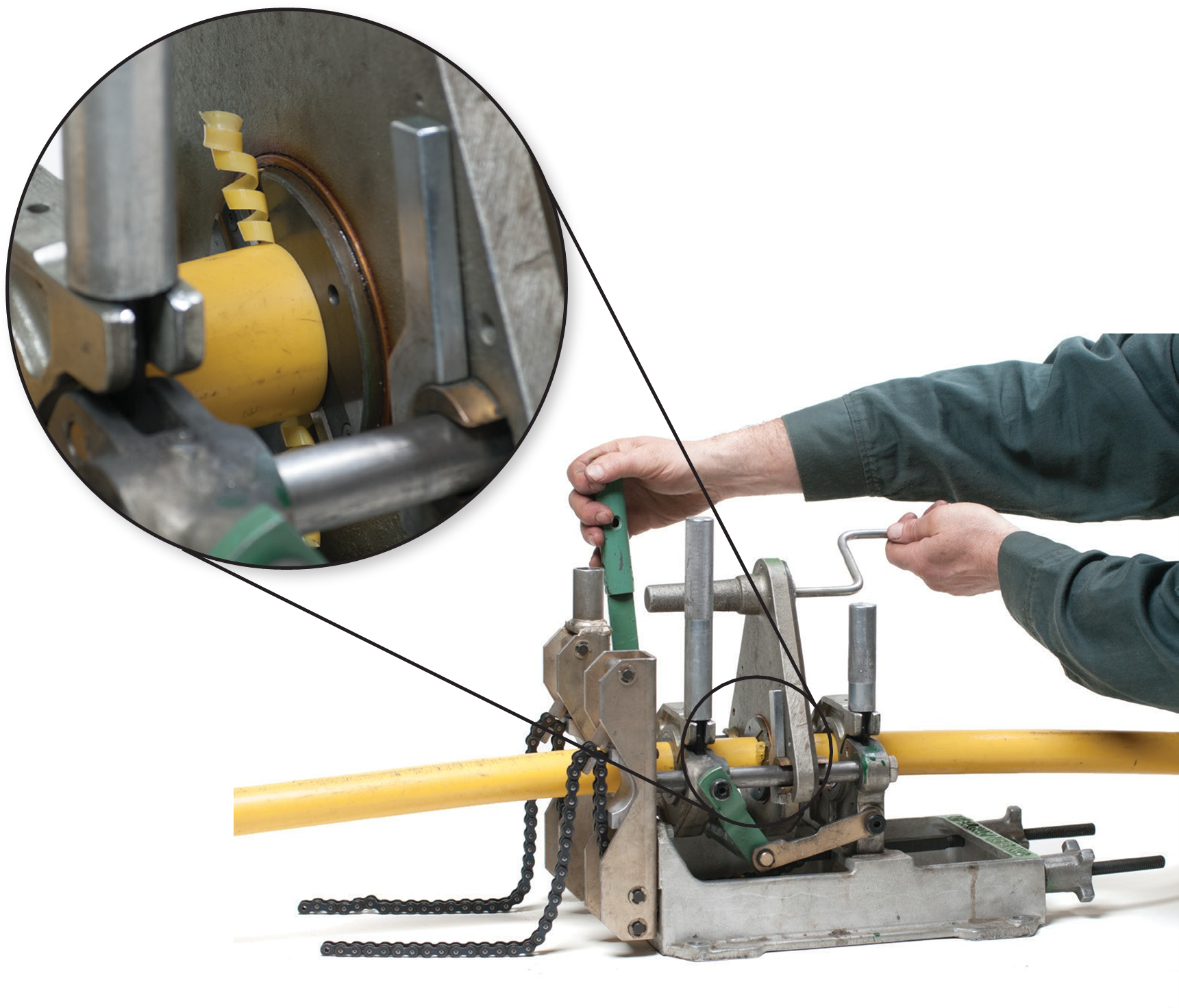
Figure 73 shows the operator checking the final alignment of the pipe ends after facing. Alignment is critical and should be perfect, with no gap between the pipe ends.
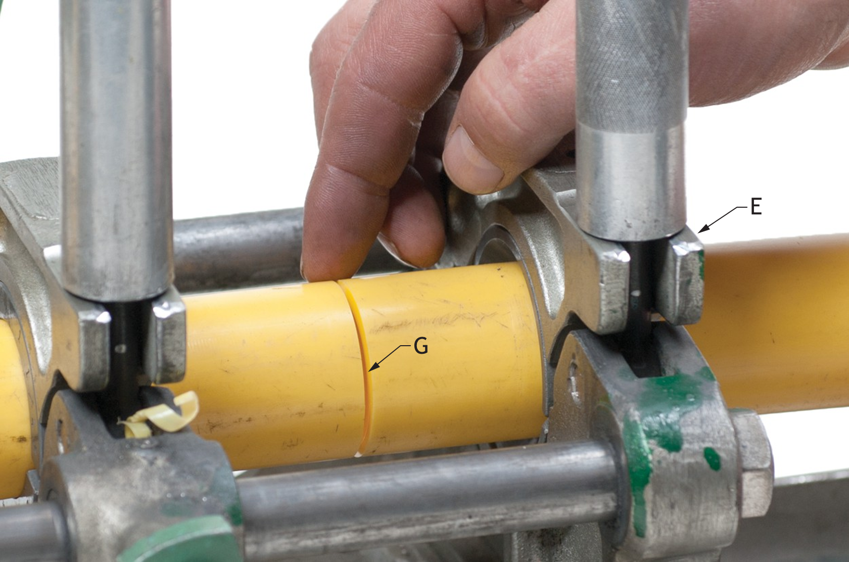
- Note the following in the above figure: the clamps (E) are positioned close to the joint.
- The pipe ends are aligned and ready for the heating iron (G).
Fusion Welding Procedure
Before proceeding with the weld, do the following:
- Make sure you have cleaned the ends of the pipe with a clean, non-synthetic cloth or paper towel. Remove burrs and debris from inside the pipe ends.
- Recheck the alignment. There should be no gaps, nicks, etc.
- Check the tightness of the cold clamps. Do not overtighten.
- Make one last check for proper alignment.
- You are now ready to install the fusion heater.
The fitting and pipe must be clean and dry. Use a clean cloth to wipe the mating surfaces. Do not touch the surfaces with your hands.
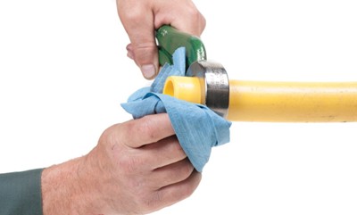
The procedures shown here are for education purposes only. Always follow manufacturer specifications, standards, and procedures. Fusion welding procedures are found in the manufacturer’s specification or in recognized approved and accepted standards. Follow the procedure carefully and adhere to all specified parameters. Failure to follow the pipe manufacturer’s procedure could result in a defective joint.
Basic Procedures
Following are general, non-specific fusion welding procedures:
- Clamping: The pipe and fitting must be held firmly to allow all subsequent operations to take place.
- Cleaning: The area of pipe that the fitting will contact must be cleaned.
- Aligning: The fitting must be properly seated on the pipe for proper alignment.
- Heating: A melt pattern must be formed that penetrates into the pipe and into the fitting.
- Joining: The pipe and fitting must be joined and the pipe fully seated within the fitting.
- Holding: The molten joint must be held immobile until adequately cooled.
- Inspecting: Visually examine the entire circumference of the joint for compliance with standards established by your company, customer, industry or local regulations.
Procedures for Butt Joint Fusion Welding
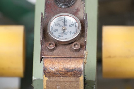
- Plug in the heater and confirm that it reaches the correct temperature according to the manufacturer’s specifications. This is normally 260°C ±4°C (500°F ±7°F). Also check the surface temperature using a Tempilstik.
- Place the heater into the assembly and bring both pipe ends into contact with the heater surface. Do not apply any pressure.
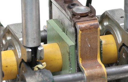
- Allow the pipe ends to form a bead (melt pattern), approximately 3 to 4 mm (0.12 to 0.16 in) in size.
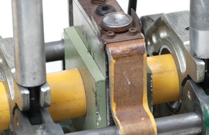
- Move the ends of the pipe away from the heater and remove the heating plate quickly. Bring the ends of the pipe together rapidly without slamming. Use just enough force to form a double roll-back bead. Too much force will push melt away from the bead, resulting in a poor fusion. Hold in position until you can touch with your finger comfortably. Wait for approximately 10 minutes before applying any stress to the joint.
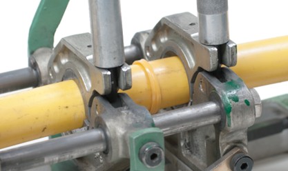
Temperature, applied pressure, and melt and cooling times are critical factors in creating a good fusion joint. With practice, you will learn when and how much pressure to apply to complete a fusion joint.
Safety Precautions for Butt Joint Fusion Welding
The heater is not explosion-proof. Take safety precautions when operating the heater in hazardous environments to prevent explosion, injury, or death. Bring the heater up to temperature in a safe environment, then unplug it before entering the hazardous environment to perform the weld. Use a clean, natural-fibre cloth to clean the heater adapter surfaces.
Clearly mark all hot surfaces to indicate they are hot. Store the heated iron in the appropriate holder to stay hot when in use or to cool off when not in use.
Precautions for Cold Weather Butt Fusion Welding
Follow these precautions when butt fusing pipe in cold weather:
- Avoid hitting the pipe ends on hard surfaces. Cold temperatures make plastic more brittle and susceptible to damage from mechanical abuse, such as impact.
- Carefully remove, by light tapping and scraping, any snow, ice, or frost from inside and outside the open ends and the areas to be clamped in the joiner. Failure to remove ice and snow could lead to incomplete fusion at the joint and slippage of the jaws.
- Use tape or paper shims if needed to prevent clamps from slipping during cold weather. Clamping inserts are usually more than adequate to prevent pipe slippage, but slippage can still occur when pipes contract in low temperatures.
- Follow the standard butt fusion steps, giving particular emphasis to the fusion steps. The time required for an initial melt bead to form will be longer than usual. Do not apply greater than normal pressure to the pipe ends.
- Bring the pipe ends together quickly after removing the heater plate from between them. Do not slam the pipe ends together.
- Protect and shelter the heating and fusion tools from high winds or rain to prevent excessive heat loss and to keep the heating tool dry at all times. The melt area should also be sheltered to reduce heat loss from the melted ends and to prevent rain or moisture from contaminating the fusion area.
Saddle Fitting with a Built-in Hole Cutter
Some saddle fittings have a built-in cutter. After fusion, the cutter can be advanced to cut the hole in the pipe. The removed cut-out section from the hole is held in the cutter, and the cutter is then repositioned at the top of the saddle. The cap is then reinstalled. The fitting may also function as a shut-off valve.
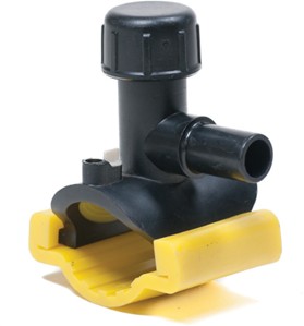
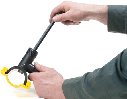
Saddle Fusion Procedure
Saddle fusion (also called sidewall fusion), is used when installing polyethylene service saddles onto compatible polyethylene pipe mains.
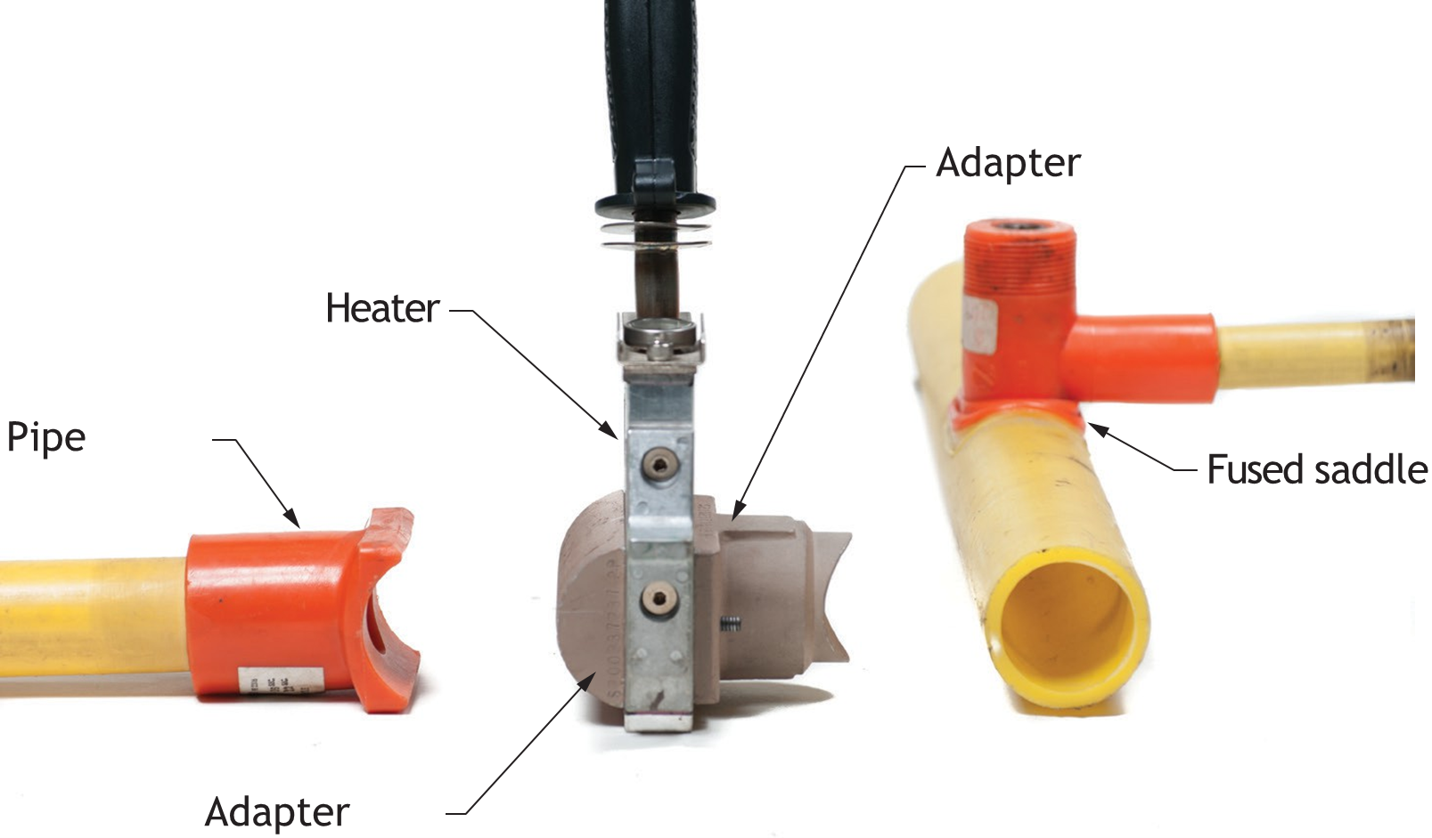
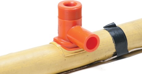
Follow this procedure when saddle fusing pipe:
- Clean the pipe surface so that it is free of dirt, oil, and water. Remove any printed ink lettering with a clean cloth.
- Install the fusion machine on the main. Ensure that the machine is adequately supported in the desired position and that it is firmly attached to the pipe.
- Prepare the surface of the pipe and fitting by first roughing with coarse emery cloth then brushing away any loose material.
- Align the fitting on the main, then tighten the fitting while applying slight pressure on the movable clamp handle.
- Check the saddle base for square alignment on the main.
- Use a Tempilstik to check the heating iron temperature, which should be 260°C ±4°C (500°F±7°F). Take care not to contaminate the actual fusion surface with Tempilstik residue.
- Quickly place the heater onto the main and remove it. Check for evidence that the heater has contacted all areas of the main. Two to three seconds of heating time should indicate this. If the main is not contacting the heater properly, the most probable reason is that the pipe is out of roundness. This can sometimes be corrected by either tightening or loosening the clamp knobs. The heater must be proven to make full contact with the main before fusion can be started.
- Place the heater between the fitting and the main. Apply firm (but not excessive) pressure while heating. Ensure that the heater is centred under the fitting. Continue to heat until a bead has formed on the pipe and on the fitting all the way around the heater. The last place that the bead should form is on the pipe, in the middle of the heating iron face
- Once the bead is at least 1.6 mm ([latex]\frac{1}{16}[/latex] in) all the way around, snap the fitting and main apart and snap the heater free. Be careful not to damage the pipe or the fitting while removing the heater. Care must be taken not to over-melt the main, as there is a risk of a blowout if the main is under pressure. The recommended maximum time for the heater to contact the main is 30 seconds.
- Bring the melted surfaces together quickly, but do not slam the surfaces together. Apply continuous progressive pressure until a proper fusion bead is formed. Maintain pressure until the joint has cooled sufficiently to allow your finger to remain comfortably on the bead.
- Remove the saddle fusion unit and inspect the fusion. The joint should have a uniform, well-aligned appearance all around. There should appear to be three beads at the fusion joint. Inspect the joint for gaps or voids or other evidence of incomplete fusion.
- Do not subject the fitting to any abnormal stresses until the fusion is sufficiently cooled, which should be in approximately 10 minutes.
- Do not drill or tap through the main until the pipe is sufficiently cool.
Precautions for Cold Weather Saddle Fusion
Follow these precautions when saddle fusing pipe in cold temperatures:
- The length of time necessary to obtain a complete melt pattern will depend not only on the outdoor (pipe) temperature, but also on wind conditions, pipe tolerances, and operator variation.
- If possible, store the fittings at room temperature before use. This will make it easier to place the fittings on the heating iron, because fittings shrink when subjected to low temperature.
After observing the above precautions, follow normal saddle fusion procedures.
Socket Fusion Welding Procedure
Follow this procedure when socket fusing pipe:
- Cut the pipe square using shear-type cutters or pipe cutters fitted with special plastic pipe cutting wheels.
- Chamfer pipe sizes 31.75 and 50.8 mm (1-[latex]\frac{1}{4}[/latex] and 2 in). Smaller sizes do not require chamfering.
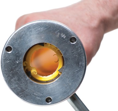
- Remove any oil or dirt from the surfaces to be joined. Sand pipe ends with emery cloth and then remove any loose material with a clean dry cloth or paper towel.
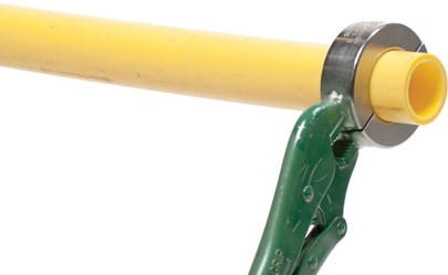
- Place the depth gauge on the end of the pipe to allow for correct positioning of the cold ring. Position the cold ring on the pipe and remove the depth gauge.
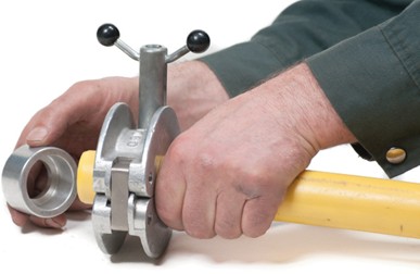
- Use a Tempilstik to check the heating iron temperature, which should be 260°C ±4°C (500°F±7°F). Take care not to contaminate the actual fusion surface with Tempilstik residue.
- Push the socket fitting into the heating iron until it bottoms out, and then place the heating iron on the pipe until it bottoms against the cold ring. Hold it there until the surfaces melt, about 5 to 40 seconds, depending upon the diameter and the temperature of the heating iron.
- Quickly remove the fitting and the pipe from the heating iron. Immediately push the fitting squarely onto the pipe until it bottoms against the cold ring. Do not twist or rotate the pipe in the socket. Hold the fitting onto the pipe for the duration of the cooling cycle (see manufacturers’ documentation).
Additional Considerations
-
- Do not subject the joint to any externally applied stresses (pulling or bending) until it is completely cool, generally in about 10 minutes.
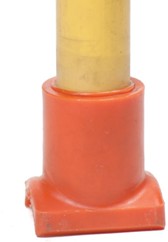
- Inspect the joint for evidence of complete fusion. This is shown by a flat melt bead pattern on the fitting that completely encircles the pipe.
- Clean the heating iron of any residue after use.
Precautions for Cold Weather Socket Fusion
Follow these precautions when socket fusing pipe in cold weather:
- Remember that the length of time necessary to obtain a complete melt pattern will depend on the outdoor (pipe) temperature, wind conditions, pipe tolerances, and operator variation.
- If possible, store fittings at room temperature before use. This makes it easier to place fittings on the heating iron because fittings shrink when subjected to low temperatures.
- The pipe also contracts in cold conditions, which may result in loose or slipping cold-clamp rings. For best results, clamp one cold-clamp ring in its normal position directly below the depth gauge, then place shim material (a piece of paper or tape) around the inside diameter of a second cold-clamp ring and clamp it directly behind the first cold-clamp ring to prevent slippage. The first cold-clamp ring will allow the fused portion of pipe to expand to its normal diameter during heating.
- Under abnormal or extreme weather conditions, use the following method to determine melt times for socket fusion:
- Place the heater onto a pipe test piece and begin timing when the cold-clamp ring bottoms out.
- After a chosen heating time, quickly remove the pipe from the heater and gouge the outer pipe wall with a screwdriver or other sharp object. The correct heating time is achieved when half of the wall thickness can be gouged out in this manner. If less than half of the wall thickness can be gouged out, increase the heating time; if more than half can be gouged out, decrease the heating time.
- Discard all gouged test pieces.
- After observing the above precautions, follow normal socket fusion procedures.
Solvent Welding Plastic Piping
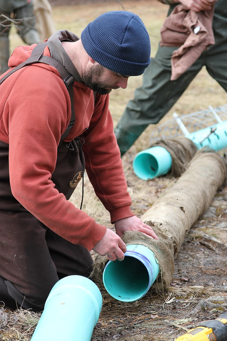
Solvent cementing is the process of fusing plastic pipe and fittings by the use of an adhesive containing a suitable active solvent system and an appropriate resin. This process is referred to as solvent welding.
Plastic piping systems are easy to install, but larger sizes (more than 50 mm or 2 in) require a degree of expertise to produce a leak-free joint.
Most plastics are joined by inserting plain-ended piping into fittings and solvent welding them together. PVC and chlorinated poly-vinyl chlorine (CPVC) piping and fittings are joined with a different type of solvent cement than acrylonitrile butadiene styrene (ABS).
Consult the manufacturer’s detailed directions on the solvent cement container. Environmental conditions, such as temperature and moisture, will affect the time required for the joint to set.

Safety Precautions for Solvent Cements
- Ensure there are no ignition sources in the area you are working, as solvent cements are flammable.
- Ensure that the work area has adequate ventilation, or wear a respirator.
- Wear protective eyewear and avoid contact of solvent cement or cleaner with your skin.
- Read the manufacturer’s Material Safety Data Sheet (MSDS) before using the solvent cement.
Solvent Cementing Joining Procedures
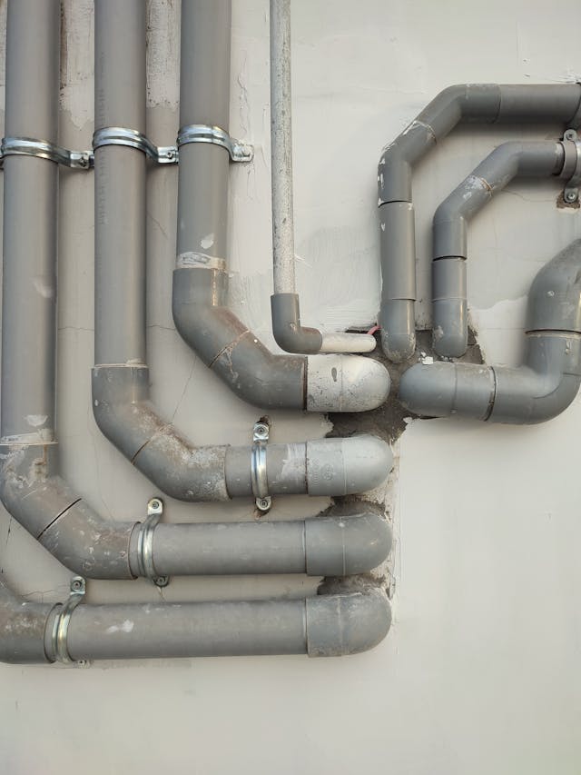
These procedures apply to all types of plastic: ABS, PVC, and CPVC.
- Pipe preparation
-
- Cutting: Cut pipe square using a hand hacksaw and miter box, a power circular or hand saw with a suitable guide, or a rotary cutter if the cutting wheel is specifically designed for cutting plastic pipe.
- De-burring and bevelling: Using a knife, de-burring tool, or coarse file, remove all burrs and sharp edges from the pipe. All pipe ends should be bevelled with a coarse file or bevelling tool. This will minimize the chance of wiping the solvent cement from the fitting socket during installation, which could result in a leaking joint. Do not use sandpaper on plastic pipes. It may remove too much material for successful joining.
-
- Fitting preparation: Before solvent cementing, all fittings should be inspected for cracks or damages. Fittings should be exposed to the same temperature as the pipe for at least an hour, to ensure that they are thermally balanced before joining.
- Cleaning: Clean the pipe end and fitting socket thoroughly. The surfaces to be joined must be clean, dry, and free of dirt and grease. Some plastics may recommend a liquid cleaner be used.
- Dry fitting: Solvent cement joints are designed so that there will generally be interference of pipe wall with the fitting socket before the pipe is fully inserted. Usually this occurs when the pipe is inserted [latex]\frac{1}{3}[/latex] to [latex]\frac{2}{3}[/latex] of the socket depth during dry fitting. Therefore, do not use this step to check your measured lengths. Sometimes, when the pipe and fittings are at their tolerance extremes or when Schedule 80 pipe is used, it may be possible to fully insert the dry pipe into the fitting until it bottoms. If this occurs, the fit should be snug. If the fit is loose or wobbly other fittings or pipe should be selected to give a proper fit.
- Priming: ABS, PVC, and CPVC are different materials. Although their cementing procedures are similar, they are different and are outlined separately below.
- ABS: Cleaner may be used to prime the mating surfaces. However, in most cases, experienced installers can achieve successful bonding without the use of a primer.
- PVC and CPVC: The use of a primer is recommended and is mandatory for all pressure applications. Our PVC-1, which is a one-step cement, does not require the use of a primer and can only be used on non-pressure applications. The function of the primer is to penetrate and soften the bonding surfaces, especially the high-gloss and hard-glaze surfaces of the pipe and fittings, before applying the cement. Apply primer to the fitting with a dauber or brush.
“One step” cement can be used when installing CPVC fire sprinkler piping.
- Solvent cementing:
-
- Choose the proper CSA-certified solvent cement.
- Using an applicator, evenly apply a heavy coating of solvent cement to the pipe and a light coating to the socket. Now apply a second coating to the pipe, ensuring that sufficient material is present to fill all gaps.
- Making certain that the cement on the pipe and fitting is still “wet,” insert the pipe into the fitting until it bottoms in the socket. Then give it a [latex]\frac{1}{4}[/latex] turn to ensure complete and even distribution of the cement. Make sure that the joint is positioned correctly, as the cement sets in a few seconds.
- If the pipe does not insert smoothly or does not twist easily, take the joint apart immediately. Apply more cement and rejoin. The use of a cleaner or primer will extend the open time and setting time.
- Hold the joint together until the cement has set. This may take up to two minutes depending upon pipe size. Avoid disturbing the joint until it is fully cured.
- Immediately after joining, wipe off all excess cement. A properly made joint will show a bead around its entire perimeter. Gaps may indicate a defective assembly resulting from insufficient cement.
Joint Integrity
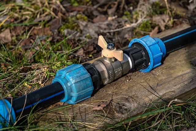
Joint integrity depends upon a tremendously wide variety of product and environmental conditions. These include size of pipe, ambient temperature, surface temperature of the joint, humidity, dry joint interference fit, and others. In general, drying times will be faster with smaller diameter pipe, higher surface temperatures, tighter interference fits, and lower humidity. Drying times will be slower when the opposite conditions exist.
Recommendations
- Avoid joining at atmospheric temperatures below 5°C (41°F) or above 32°C (90°F) when exposed to direct sunlight. For work outside of this preferred range, refer to the sections below on hot-, cold- and wet-weather cementing.
- Allow at least 48 hours of joint drying time before a joint is moved or subjected to any internal or external pressure. When in doubt about proper cementing techniques under particular conditions, contact the solvent cement manufacturer for expert advice.
Cementing Under Wet Conditions
Moisture inhibits the bonding of plastic pipes and fittings. In failed joints a white film or residue often appears, indicating the presence of water during the joining process. Cementing can be done in wet weather and in wet environments but it is imperative that the mating surfaces be dry when the joint is made.
The following suggestions may help in wet situations:
- Work under a cover or canopy to keep rain off the pipe and fittings.
- Use a cleaner or primer to aid in the removal of moisture.
- Work quickly after drying the pipe and fitting to avoid condensation.
- Use a very fast-drying and fast-setting cement to limit the period of time when the joint is vulnerable to moisture. A fast-setting cement requires the worker to apply more cement and to work very quickly to ensure that the cement is still fluid when the pipe is inserted into the fitting.
- Allow a longer cure time before the system is tested or used.
Hot Weather Cementing
When atmospheric temperatures are above 32°C (90°F), certain precautions have to be taken to avoid excessive solvent evaporation from the cement. Such evaporation may cause the cement to set prematurely and adversely affect joint integrity.
The following steps can reduce these challenges:
- The surface temperature of the mating surfaces should not exceed 45°C (113°F) at the time of assembly. Shade or shelter the joint surfaces from direct sunlight for at least an hour prior to joining and also during the joining process. Swabbing the surface to be cemented with cleaner may reduce the pipe temperature; wet rags may also be used, provided the parts are thoroughly dried before primer or cement are applied.
- Make cement joints during the cooler, early morning hours.
- Apply cement quickly. On 15 cm (6 in) and larger pipe we recommend that two workers apply cement to the pipe surface while a third applies it to the fitting socket.
- Join pipe to the fitting as quickly as possible after applying cement.
- To minimize solvent loss, keep cement container closed or covered when not in use.
Cold-Weather Cementing
Working in freezing temperatures is never easy. However, if the job of solvent cement welding is necessary, you can do it successfully with proper solvent cements. By following the manufacturer’s standard instructions and using a little extra care and patience, successful solvent cemented joints can be made at temperatures even as low as –26°C (–14.8°F). In cold weather, solvents penetrate and soften the plastic pipe and fitting surfaces more slowly than in warm weather. In addition, the plastic is more resistant to solvent attack, making it more important to pre-soften surfaces withan aggressive primer. Because of the slower evaporation, a longer cure time is necessary. Cure schedules provided by the manufacturer will allow a margin for safety, but for colder weather, more time should be allowed.
Suggestions for Quality Joints in Cold Weather
- Prefabricate as much of the system as is possible in a heated work area.
- Store cements, cleaners and primers in a warmer area when not in use and make sure they remain fluid.
- Joints that must be made outside should be protected with a portable shelter and heated with indirect heat to surface temperatures above 5°C (41°F) before joining. The shelter and heat should remain in place for at least two hours after joint assembly.
- Although PVC-1 (one-step) cement can be used in cold weather, it is extremely important that extra care be taken when applying the cement, so that proper penetration and softening of the pipe and fitting surfaces are achieved. The use of a primer when using PVC-1 during an extreme cold-weather installation will be beneficial to the final results if shelters and heating set-ups cannot be done in the welding area.
- Take special care to remove moisture including ice and snow from the surfaces to be joined. On PVC and CPVC pipe and fittings the surfaces must be cleaned with a manufacturer-approved cleaner.
- Before assembly, after the pipe has been cut, cleaned and dry-fitted as per the instructions on the label, primer must be used to soften the joining surfaces on PVC or CPVC installations before applying cement. On ABS installations, cleaner may be used as the primer. More than one application may be necessary.
- Allow a longer cure period before the system is used. A heat blanket may be used to speed up the set and cure times.
- It is extremely important to read and follow all of the manufacturer’s directions carefully before installation. For all practical purposes, good solvent-cemented joints can be made in very cold conditions, with proper care.
Caution: Do not attempt to speed the setting or drying of the cement by applying direct heat to the solvent-welded joint. Forced rapid drying by heating will cause the cement solvents to boil off, forming porosity, bubbles and blisters in the cement film.
Estimating Solvent Cement Requirements
The actual number of joints can vary considerably due to installation conditions and techniques, tolerance variations, and socket depths. Since the cement is the least expensive material being used, it is better to use too much cement than not enough.
Refer to manufacturer documentation.
Set Times and Cure Schedules
During the initial setting of the cement (approximately 2 minutes), the joint should not be moved or disturbed. Numerous factors, such as application conditions and the specific cement used, affect the actual cure rates, which may be faster or slower than the times indicated. In damp or humid weather, allow 50% more set time and cure time; extended set times are required for chemical applications.
Refer to manufacturer documentation for exact curing schedules. The initial set schedule is the necessary time needed before the joint can be carefully handled.
PVC and ABS Testing
For testing, refer to manufacturer documentation and applicable local code requirements.
Joining ABS to PVC Piping
Transition solvent cement is solvent cement used to join ABS drainage and PVC drainage pipe and fittings. This solvent cement is white in colour and is typically used only for a single transition joint within a system. You are not permitted to switch back and forth from ABS to PVC several times. This solvent cement is often used to connect ABS DWV pipe to PVC sewer pipe after the ABS pipe leaves the building. Procedures for joining are the same as for ABS and PVC.
Threaded Piping Connections
Various types of iron, steel, heavy copper, and plastic piping may have threaded ends. The most common type uses external threads that are joined with internally threaded fittings.
Threading pipe is an essential skill in the piping trades. Pipe threads are widely used to join pipe and fittings. You must be able to produce high-quality threads and assemble leak-proof joints. Poor threading can lead to serious problems, especially in gas or pressurized systems.
A common question is, “How tight do you tighten the pipe and fittings?” The answer is: tight enough to prevent leaks, but not so tight that the fitting is damaged. Over-tightening may stretch a malleable fitting or crack a cast iron fitting. The correct feel is developed through experience.
The number of pipe threads that remain exposed after you have finished tightening the fitting onto the pipe will give some indication of the joint quality. Typically, two to three threads should remain visible. If no threads are visible, the joint may be over-tightened. If too many threads are visible, the joint may be under-tightened.
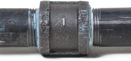
Procedures for Threaded Jointing
Installation of threaded joints involves the cutting of threads and assembling the joint. Threads may be cut using a power threader or by hand. When cutting threads by hand, follow these steps:
- Select the proper size of die.
- Clean the pipe surface. Be sure the end is square and free of burrs. Chamfering the pipe end will make it easier to start the die.
- Mount the threader on the pipe with the die’s leading threads facing the pipe.
- Apply thread cutting oil.
- Apply pressure to start the die on the pipe.
- The thread length is correct when the outer surface of the die is even with the end of the pipe (for full-width dies).
- Remove the die and clean the threads with a brush or rag.
- Apply an approved joint compound or tape that is to the external threads only.
- Hand-tighten the fitting, then tighten to the required degree using the correct wrench.
Precautions for Threaded Jointing
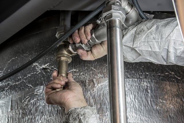
- Threaded components and threaded ends should be examined before assembly for cleanliness and continuity of threads, and to ensure they conform with applicable standards.
- Compound or lubricant used on threads must be suitable for the service conditions and should not react unfavourably with either the service fluid or the piping material.
- Threaded joints that are to be seal-welded are made up without thread compound or lubricants.
- When a design requires threaded piping to be seal-welded, seal welds must cover all exposed threads.
Compression and Flared Joint Guidelines
For the proper installation and maintenance of compression and flared fittings, use the following guidelines:
- Inspect flare surfaces for imperfections before assembly.
- Where the manufacturer’s instructions call for a specified number of turns of the nut, count these from the point at which the nut becomes finger tight.
- Cut ends square using the recommended method as per the type of material.
- Deburr inside and outside for proper entry into fitting and to prevent system contamination and or restricted flow.
- Clean tube ends. Remove all filings, chips, and grit before attachment of fittings.
- Do not force an improperly fitted tube line into the fittings. The fabrication of tube lines (your bend angles and measured lengths) must be accurate. Check to see that the tube end easily enters the fitting in proper alignment.
- The tube end must be bottomed against the shoulder in the fitting body. This is necessary to prevent movement of the tube, while the nut forces the ferrule to grip the tube and to seal through any imperfections that may exist on the outside tube surface.
- Use two wrenches. Never permit the fitting body to rotate during tube end makeup. Assemble port connectors to components first and hold this with your first wrench while making up the tube joint. All types of union bodies must be held while each of the tube ends is made up.
Other Types of Pipe and Tube Jointing
Other types of pipe and tube jointing methods include:
- Mechanical joints with external clamping and sealing components, such as elastomeric gaskets and sealing rings.
- Insertion jointing where the pipe is pushed into the fitting, sealed with O-ring-type gaskets with a variety of profiles to suit the particular manufacturer’s fittings and applications. These connections often include components that use compression forces to hold the pipe together and seal the joint.
Many types of piping can be joined with special types of fittings, such as mechanical joint couplings used with cast iron drainage and vent piping, roll and cut grooved pipe couplings and fittings, compression fittings, slip-on fittings, or insert fittings. In some cases, plumbing codes will restrict where and when these types of fittings and jointing methods can be used.
Procedures for these types of fittings may require the pipe ends to be prepared in ways such as the following:
- Measuring
- Cutting the pipe or tubing ends square
- Reaming, de-burring or chamfering the pipe ends
- Cleaning the pipe or fitting end and sockets ends or checking both inside and outside for debris or damage
- Applying lubricants on the pipe or fitting when required
- Ensuring correct arrangement of any clamp components, such as retaining rings, washers sleeve, seals, etc.
- Attaching the clamp and any component parts fully to one end of the pipe or fitting
- Inserting fully the other pipe or fitting end into the clamp
- Aligning the pipe, fittings, and clamps correctly
- Tightening any components, keeping joint alignments as you proceed, following any specified tightening sequences as required to ensure proper seal and joint strength
- Testing all piping system as required by the engineering, manufacturers’ and code specifications
Mechanical Joint Method
Mechanical joint or zip couplings use screws or bolts to tighten a stainless-steel collar that compresses a neoprene or rubber sleeve (gasket) around the joint. These couplings can join plain-ended pipe and fittings.
O-Ring or Gasket Joints (Slip-On Joints)
Hub-and-spigot piping and fittings can be joined with O-rings or special elastomeric gaskets. O-rings are usually rubber or neoprene ring gaskets that fit over the spigot pipe end and inside the hub of the fitting. The O-rings may be different profiles to match a particular pipe manufacturer.
The O-ring is held in place by the tight fit of the pipe and fitting and seals the pipe joint. In some pipes, a groove is machined into the hub end of the pipe to hold the O-ring in place. This type is often referred to as a slip-on joint. This method of joining is commonly used with ductile iron water pipe.
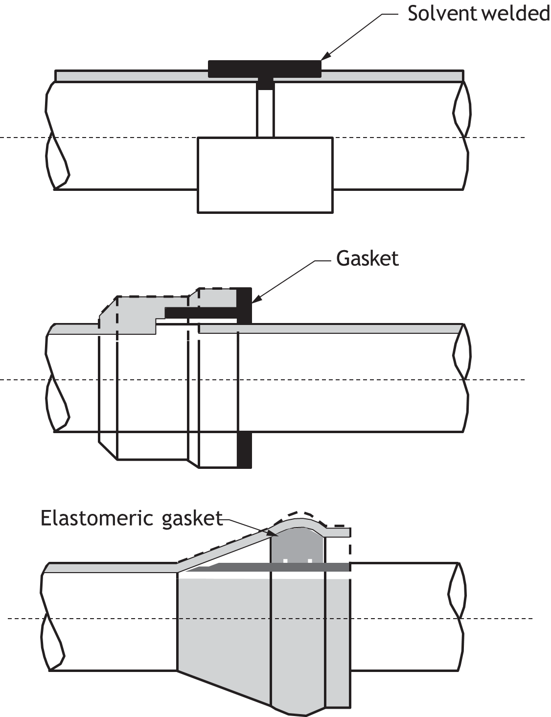
For calculation of fitting allowances, see the calculations for piping measurements in Block B: Tools and Equipment.
Flanges
Flanges may be used to join plastic or metal piping. Flanges may be welded or screwed to metal pipe. Plastic flanges may be solvent welded or screwed together.
When measuring for flanged piping, allow for the thickness of the gaskets that will be installed between the flanges (Figure 95).
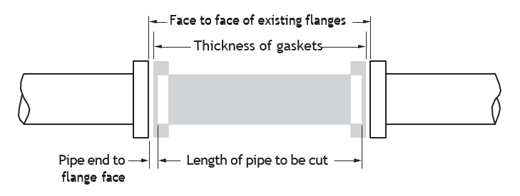
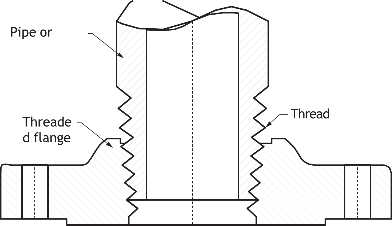
1. Threaded flange 2. Thread 3. Pipe or fitting (BC Industry Training Authority, 2019). CC BY-NC-SA 4.0
When installing a threaded flange, fully tighten the flange onto the pipe so that the end of the pipe is almost even with the face of the flange. Place the flanges on each piece of pipe together with a sealing gasket between each face. Align the bolt holes in each flange, then insert and tighten bolts to complete the seal.
Making a Flanged Joint
There are four basic steps in making a flanged joint:
- Clean all surfaces on the parts, remove any grit or grease from the flanges, and make sure the gasket is clean.
- Support the flanges and align the bolt holes. Support the part that you are installing and align the flanges both face-to-face and hole-to-hole (this is known as timing flanges). Bevelled punches are often used to do this.
- Insert the gasket. For ring gaskets, insert the bottom bolts first, rest the gasket on them and then insert the rest of the bolts. For full-face gaskets, first insert a bottom bolt through one flange, one hole of the gaskets and the other flange. Then roll the gasket into place and insert the other bolts.
- Tighten the bolts evenly using the crossover method. Apply a bit of thread lubricant to each bolt and run up the nuts by hand as far as they will go. Then use a wrench to snug the bolts using the crossover method. The crossover method ensures that bolts are tightened evenly. Start with the top bolt, then tighten the opposite bolt on the bottom, then tighten the bolt on the left side, then the right side, etc. Tighten all the bolts, following the same numerical sequence shown in Figure 97. Be sure to not over-torque the bolts.
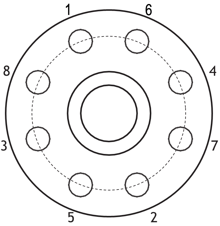
Note: Sequence and torque method and values vary depending on flange size and ratings, temperature, pressure, etc. Always follow the manufacturer’s recommendations and engineering specifications specific to the installation. For more information on bolt tightening sequence, refer to the section on valves in IPT’s Pipe Trades Handbook.
Flange Alignment: Checking Highs and Lows
When installing a flange, it is critical to align the inside diameters so that they are exactly centred. Do this by making sure the OD of the mated flanges are flush with each other (adjust so the highs and lows are flush). If the inside diameters, including the gasket, are not flush, inside turbulence is created, resulting in friction loss and/or noise and erosion.
High and low piping termination describes surface misalignment of the outside diameters of pipes at the point where the two pipes are joined.
Bolt-Tightening Torque
Tighten the bolts in the correct sequence and torque.
- Torque bolts in stages
- Follow the recommended sequence (30%, then 60%, then final value)
▸ If this sequence is not followed, the flanges can be misaligned. Then, regardless of the amount of subsequent tightening, they cannot be brought back to parallel. This more of a problem on metallic gaskets than on non-metallic ones.
On high-pressure, high-temperature applications, the flanges should be retightened after 24 hours at operating pressures and temperatures to compensate for any relaxation or creep that may have occurred.
Common Practices When Completing Flanged Joints
Be sure to:
- Inspect the gasket seating surfaces for damage.
- Make sure the gasket material is suitable for the contents of the system. Look for any defects or damage in the gasket.
- Inspect and clean each stud or bolt, each nut, each washer and the facing on the flanges against which the nuts will rotate.
- Lubricate all thread contact areas and nut facings. When flanges are to be subjected to high temperatures, consider using an anti-seize compound to facilitate subsequent disassembly.
- With raised face and ring gasket installation, loosely install the stud bolts on the lower half of the flange.
- Insert the gasket between the flange faces to allow the bolts to centre the gasket on the assembly. Install the balance of the bolts and nuts and bring all to a hand-tight or snug condition.
Pipe Flange Assembly
Using a Torque Wrench
A torque wrench is a tool used to precisely apply a specific torque to a fastener, such as a nut or bolt. It is used where the tightness is critical. The torque wrench is used to measure the torque applied to the fastener so it can be matched to the torque tension specifications required for an installation.
General Torque Wrench Guidelines
Follow these general rules when using a torque wrench:
- Never over-torque a fastener. Over-torquing can cause a fastener to stretch beyond normal limits, causing it to break or come loose.
- Never under-torque a fastener. The fastener could come loose or break.
- Follow torque specifications and sequences for torque application.
- Apply fastener lubricants as required by the manufacturer.
- Read and follow the manufacturer’s direction for the torque wrench you are using.
- Do not re-use a fastener if it was installed with an impact wrench.
- Do not use a torque wrench to remove a fastener, especially if it was installed with an impact wrench. You could damage the torque wrench.
Fastener (Bolt) Failure
Fasteners such as bolts could fail under the following circumstances:
- Overloading caused when the torque force exceeds the fastener strength. The fastener may loosen or shear.
- Over-tightening (over-torquing) may cause damage to the threads or deforming of the parts.
- Under-torquing may cause the joint to come loose. It may also allow the joint to flex and thus fail when fatigue occurs.
- Brinelling caused by poor-quality washers, leading to a loss of clamp load and failure of the joint.
- Disintegration of a part due to oxidation or other forms of corrosion. This is why fasteners must be lubricated unless stated otherwise by the equipment manufacturer.
Brinelling is a material surface failure caused by contact stress that exceeds the material limit. This failure is caused by just one application of a load great enough to exceed the material limit. The result is a permanent dent or a permanent deformation of the metal surfaces.
Click-Type Torque Wrench Procedures
- Preset the torque value on the torque wrench as specified by the equipment manufacturer
- Torque the fastener using the specified tightening sequence to the point where the desired torque is reached. Listen for a click sound, which indicates that the torque value has been reached.
- Reset the torque value to zero before putting the wrench away.
For more information on torquing, refer to IPT’s Pipe Trades Handbook (Section 5 Gasketed Joints).
Standard Flange Bolts and Flange Stud Bolts
Bolt up the flanges using stud bolts and the correct bolt-tightening sequence.
The flange stud bolt nuts, located on each side of the mated flanges, must have the same number of threads exposed past the nuts. The 2H or similar identifying mark must be visible.
Stud Bolt Grade Markings
Thread rods and nuts must be marked by the manufacturer with a unique identifier to identify the manufacturer or private label distributor, as appropriate. Figure 98 shows examples of ASTM markings.
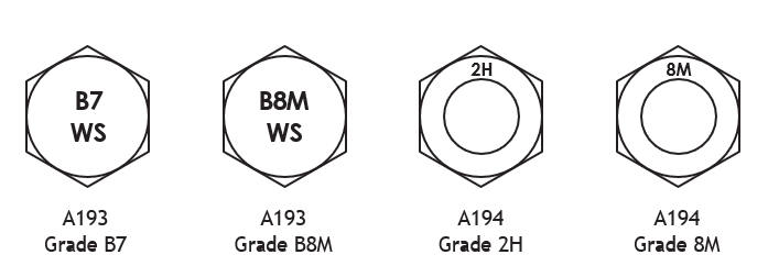
Corrugated Stainless Steel Tubing (CSST)
Specialty piping such as Corrugated Stainless-Steel Tubing (CSST) is flexible gas piping suitable for connection to natural gas or propane appliances, and for natural gas and propane piping systems. CSST and its related fittings may have manufacturer-specific methods of installation and jointing that require specialized training. Figures 99–106 show examples of CSST tubing and fittings.
The following information is generic in nature. On the job, you must refer to the specific manufacturer specifications when selecting fittings and installing corrugated stainless-steel tubing (CSST) piping systems.
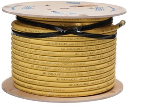
Straight fittings connect the flexible gas tubing to gas supply, distribution manifolds, or gas appliances.
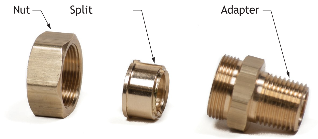
Tee fittings create a branch line on tubing runs. Couplings allow for the splicing and additions to the flexible gas tubing.
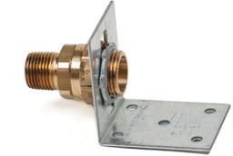
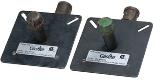
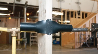
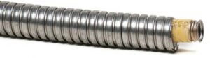
General Installation Requirements for CSST
These installation requirements must be used in conjunction with all applicable building standards and codes. In the event that there is a conflict between these guidelines and the local code, the more stringent requirement will take precedence.
- Store all tubing, fittings and hardware in a clean, dry location prior to installation.
- Temporarily plug or tape closed the open ends of tubing prior to installation, to prevent entrance of dirt, dust or other debris.
- The protective plastic jacketing should be kept in place as much as possible to protect the tubing from corrosive threats. Contact with chemicals containing chlorides must be followed by a thorough rinse and wipe dry. This includes fluxes used to solder copper tubing and acid-based cleaners used to wash masonry.
- Keep tubing away from sharp objects.
- Only qualified installers trained in the individual manufacturer’s installation instructions can install CSST flexible gas piping.
- Use only the components provided or specified by the manufacturer (including striker plates and armour conduit).
- Never use CSST flexible gas piping or system components as a ground electrode or as a grounding path for appliances or electrical systems.
- CSST flexible gas piping routed in a location that is concealed, constrained and within 7.5 cm (3 in) of a potential threat must be protected against damage by protection devices listed in the manufacturer’s instructions. Contact with sharp objects or harmful substances should be avoided.
- Protect concealed tubing from puncture threats using provided striker plates at all points of penetration through studs, joists, plates or similar structures. The extent of protection is defined in the manufacturer’s documentation.
- CSST greater than 25.4 mm (1 in) inside diameter installed within hollow cavity walls made of 2 × 4 construction shall be protected along the entire concealed length in the manner and using the shielding devices specified by the manufacturer.
- The width of the installed striker plate, at the points of penetration through wall studs, floor joists, plates, sills, etc., shall be out at least 1.5 times the outside diameter of the tubing.
- Temporarily plug or tape closed open ends of tubing prior to installation, to prevent entrance of dirt, dust or other debris.
- Keep protective yellow jacketing in place as much as possible to protect the tubing from corrosive threats. Contact with chemicals containing chlorides must be followed by thorough rinse and wipe dry. This includes fluxes used to solder copper tubing and acid-based cleaners used to wash masonry.
- Installation clearance holes for routing CSST are to be approximately 12.7 mm ([latex]\frac{1}{2}[/latex] in) greater than the OD of the CSST. Drilling of any structural member must be in conformance with the local building codes. See manufacturer’s guidelines for the recommended drill hole sizing.
- Support CSST tubing with pipe straps (metal pipe straps are preferred), bands or hangers suitable for the size and weight of the tubing, at intervals specified in manufacturer’s documentation and codes.
- Do not put stress or strain on the tubing and fittings. Avoid sharp bends, stretching, kinking or twisting of the CSST tubing.
- Sizing of CSST must be performed using the capacity tables found in the manufacturer’s guidelines.
- Don’t connect CSST flexible gas piping to movable appliances. Connections to movable appliances such as ranges and clothes dryers should be made with a flexible gas appliance connector.
- Regulators are suitable for multi-poise mounting. When using a vent-limiting device, the regulator must be mounted in a horizontal upright position. For outdoor venting, the vent line must be at least the same size as the vent connection and no longer than 914 cm (30 ft) before upsizing. When mounting a regulator outdoors, remove vent limiting device and position regulator inverted with open port down.
- A manifold assembly shall include a shut-off valve ahead of the regulator and shall be installed in an accessible location so that the regulator can be inspected, maintained and serviced, if necessary.
- CSST shall not be buried directly in the ground or directly embedded in concrete (i.e., patio slabs, foundations and walkways). When it is necessary to bury or embed CSST, the tubing shall be routed inside a non-metallic, watertight conduit that has an inside diameter at least 1.27 cm ([latex]\frac{1}{2}[/latex] in) greater than the OD of the CSST tubing. For ends of conduit installed outdoors, the conduit shall be sealed at any exposed end to prevent water from entering. No mechanical joint fittings are permitted within the conduit. Note: CSST must be buried in accordance with all local building codes.
CSST flexible gas piping system must be pressure-tested for leaks during rough construction, in accordance with all local codes. In the absence of local requirements, test in accordance with Part 4 of the NFPA 54, National Fuel Gas Code ANSI Z223.1 and/or CSA B149.1 Installation Code or in accordance with the requirements of the applicable local codes. For a one-part pressure-test, the regulator should be removed from the system. For a two-part test, the regulator should be isolated from downstream test pressures.
- CSST tubing installed along the outside of a structure (between the ground and a height of 183 cm [6 ft]) in an exposed condition shall be protected from mechanical damage inside a conduit or chase. A conduit or chase is not required if the tubing is installed in a location that will not subject the CSST to mechanical damage.
- Don’t use CSST tubing as a means of support for the gas meter. Also check with your local code official or authority having jurisdiction on meter hook-ups. Some restrictions may apply. Local code requirements will always take precedence.
- For a piping system that includes manual gas valves listed as complying with requirements, the instructions shall state that these valves shall not be installed outdoors.
- When using CSST through metal enclosures, the CSST tubing must be protected by grommets, bushings or armour, PVC tape, shrink sleeve material or a minimum of four wraps of minimum 10 mil duct tape. This is to ensure that no physical contact will be made between the metal and the CSST tubing that would cause mechanical wear.
- Physical contact between CSST and a metallic chimney liner and/or vent is prohibited. If this physical separation cannot be specifically identified in the local building code and achieved or, any local building code requirements cannot be met along the entire length, then rerouting of the CSST is required unless such installation is specifically permitted by the local building authority.
- Gas code requirement: CSST systems and copper tubing shall only be connected to an appliance secured in place (not movable). (CSA B149.1 6.11.5)
- Gas code requirement: CSST system piping or copper tubing shall not be used to connect to a meter, unless the meter assembly is independently supported. (CSA B149.1 6.14.8)
- Gas code requirement: CSST tubing shall be protected against physical damage in accordance with the manufacturer’s certified instructions and with the gas code. (CSA B149.1 6.16.12)
- The corrugated stainless steel tubing system has a number of essential hardware and design differences from conventional gas piping using rigid steel pipe and copper tubing. These differences are described as follows:
- In many applications, the tubing is sized for individual gas appliance loads and is therefore usually small in diameter. The tubing may also be installed in a parallel fashion from a central distribution manifold rather than a series layout commonly used for rigid pipe systems.
- CSST is pulled through the structure similar in fashion to electrical wiring and therefore requires different handling and installation techniques than rigid pipe.
- Rigid termination of the tube ends is required.
- Flexibility and strike plates protect the CSST allowing it to be run in concealed spaces.
Identify CSST tubing, Fittings, and Supports
You should be able to identify and name corrugated CSST tubing, fittings, and supports, and identify the basic joint connection methods. You will also need to know how to describe basic installation requirements for CSST tubing. The following image shows the parts of a CSST joint.
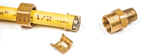
Detailed CSST Assembly Procedures
The following is a manufacturer’s installation procedure for completing a CSST joint. Other manufacturers of this CSST tubing system will provide similar procedures. But you will need to apply the installation requirements particular to the manufacture tubing you are using.
Important: Be advised that it is necessary that you comply with any applicable installation codes, such as the Gas Code.
Step 1: Cut to Length
Cut tubing to the desired length, leaving approximately 2.5 cm (1 in) for fitting the attachment. Centre the cut between two corrugations. Use light roller pressure with extra rotations in one direction to leave tubing round and free of burrs. Note: To ensure a quality flare, make all cuts on a straight section of tubing.
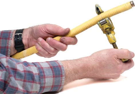
Step 2: Strip Jacket
Using a utility knife, strip the jacket back to the valley of the second corrugation. Do not cut the jacket in such a way that the sealing surface of the tubing is scored. The short piece of jacket can easily be removed by placing the utility knife blade under the jacket to peel the jacket off.
Caution: Tube ends are sharp. Use care when handling.
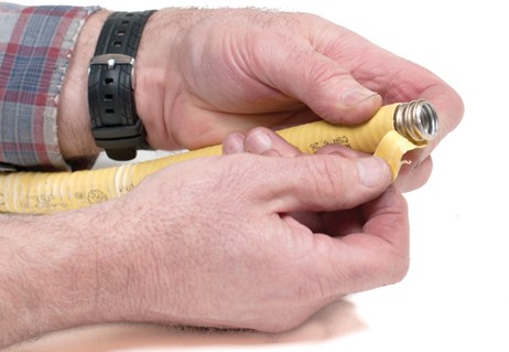
Step 3: Install Nut and Bushings
Thread fitting body into appliance or manifold. Slide nut over tubing. Separate bushings and position into the valley of the first corrugation. Leave one corrugation exposed between the end of the bushings and tubing. At this point, the bushings will begin to capture the jacket for a contaminant-resistant seal.
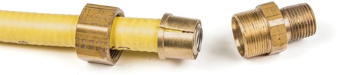
Pipe dope or sealant must not be used inside the fitting prior to assembly.
Step 4: Position Bushings
Insert bushings into fitting body. A small amount of resistance indicates the bushings are being compressed to further capture the jacket. Note: The piloting feature of the bushings ensures the tubing is aligned properly with the fitting body for a uniform flare and a gas-tight seal.
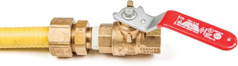
Step 5: Tighten the Fitting
Slide nut over bushings and thread onto fitting body. There will be some resistance as the nut begins to compress the tubing and create the double wall flare. Continue to thread the nut until resistance to wrenching increases greatly, and the double wall flare is tightly seated.
Note: During the tightening process, rotate the nut only. Do not rotate the fitting body. Any portions of the exposed stainless-steel tubing shall be wrapped with tape or sleeved to prevent threats by acids or chloride-based cleaning solutions for masonry. Self-bonding silicone tape is recommended here for durability.
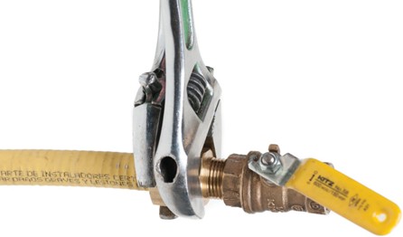
Consult the manufacturer’s torque values or specifications for tightening instructions.
Describe Basic Installation Requirements for CSST Tubing
CSST can be installed in a variety of ways. Ensure that the manufacturer’s instructions are followed and conform to applicable codes, such as the Gas Code.
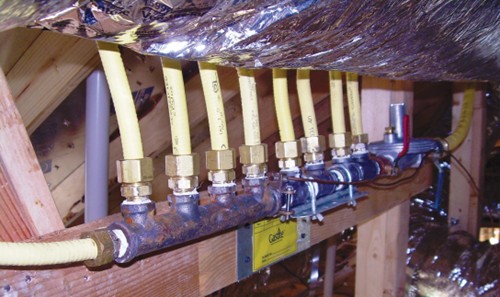
A manifold assembly using a pounds-to-inch regulator should include a shut-off valve ahead of the regulator. It should also be installed in an accessible location so that the regulator can be inspected, maintained and serviced, if necessary.
CSST Tubing Basic Installation Practices and Tubing Protection
Open ends of CSST tubing are to be temporarily plugged or taped closed prior to installation to prevent entrance of dirt, dust or other debris.
CSST must be protected from electrical contact with stray electrical currents, or static buildup. Protection is provided by bonding (grounding) the tubing to a ground rod or source, as required by electrical codes. The ground clamp must be clamped directly (touching) to a metal component of the CSST system, not clamped over the plastic sheath.
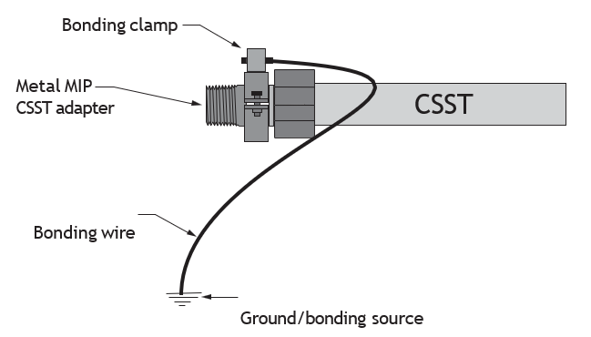

 Never use CSST flexible gas piping or system components as a ground electrode or as a grounding path for appliances or electrical systems. Refer to the manufacturer’s instructions. Direct bonding of CSST will be required. When installing CSST tubing, take care to maintain as much separation as reasonably possible from other electrically conductive systems in the building. Any metal piping system, including CSST, that is not adequately bonded may cause any electrical charge to arc from one system to another. Arcing can cause damage to CSST. Ensure the bonding of the CSST is complete to a ground rod or the electrical panel. A qualified electrician may be responsible for this work.
Protection of Concealed CSST
The following are examples of methods used to protect concealed CSST tubing—always refer to manufacturer installation guides and the authority having jurisdiction [AHJ].
- Protect concealed tubing from puncture threats, using the striker plates provided, at all points of penetration through studs, joists, plates, or similar structures.
- For all points of penetration less than 2 in (50.8 mm) from any edge of a stud, joist, plate, etc., a striker plate is required to provide protection at the area of support and within 5 inches (127 mm) of each side (if appropriate) of the support.
- At points of penetration 2 to 3 inches (50.8 to 76.2 mm) from any edge of a stud, joist, plate, etc., a striker plate is required to provide protection throughout the area of support.
- At points of penetration greater than 3 inches (76.2 mm) from any edge of a stud, joist, plate etc., no protection is required.
Protecting CSST from Puncture Damage
CSST tubing can be damaged after it has been installed and when the wall cladding is attached to the rough wall framing. As the cladding is attached, screws or nails are driven through wall cladding and can penetrate the CSST tubing. This results in gas leakage.
To prevent this from happening, metal shields called striker plates or steel conduit are installed at locations where a nail or screw will likely be used. CSST tubing routed horizontally through studs should also be protected from puncture threats between the studs with provided shielding devices.
The following diagrams show where the strike plates are used.
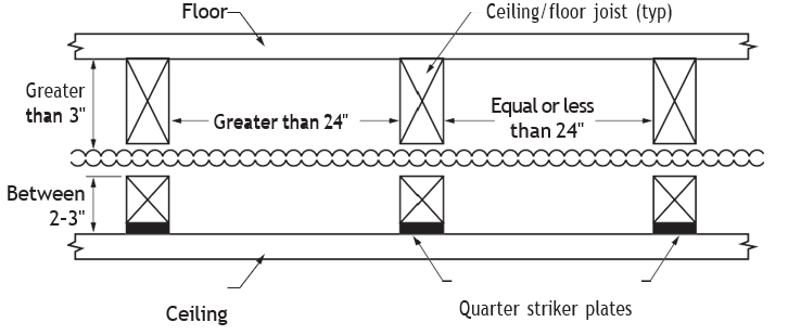
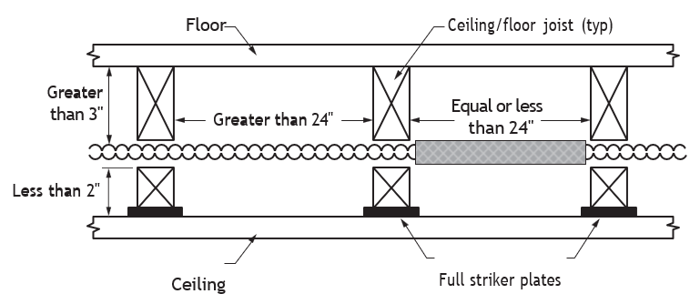
CSST tubing needs to be supported with pipe straps, bands, or hangers suitable for the size and weight of the tubing. The supports should be placed at intervals not to exceed those shown in the tables outlined in the manufactures installation guide and/or applicable codes.
Avoid undue stress or strain on the CSST tubing and fittings. Also avoid sharp bends, stretching, kinking, or twisting of the CSST tubing.
The following pictures show examples of striker plates and steel conduit used to protect CSST tubing from damage from penetration by nails, screws, or other items used to attach drywall or other wall claddings or attachments.
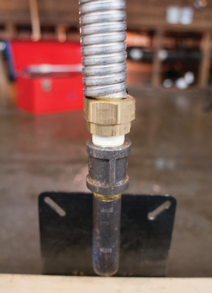
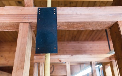
The width of the installed striker plate, at the points of penetration through wall studs, floor joists, plates, sills, etc., should be out at least 1.5 times the outside diameter of the tubing.
Flexible gas piping routed in a location that is concealed, constrained, and within three inches of a potential threat should be protected against damage by approved protection devices, as shown below.
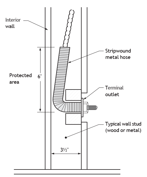
The following is an example of a grommet used when CSST passes through a metal stud.
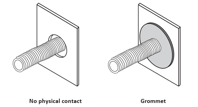
A grommet keeps CSST centered in the hole, avoiding contact damages from sharp edges.
For installations buried underground, concrete, asphalt or embedded in concrete, CSST flexible gas piping must be routed in a non-metallic watertight conduit that has an inside diameter at least ( [latex]\frac{1}{2}[/latex] in) inch larger than the outside diameter of the tubing. No mechanical joints are permitted within the conduit.
 Self-Test D-1.6: Install Tubing and Pipe
Complete Self-Test 1.6 and check your answers.
If you are using a printed copy, please find Self-Test D-1.6 and Answer Key in the Appendix at the end. If you prefer, you can scan the QR code with your digital device to go directly to the interactive Self-Test.

References
BC Industry Training Authority. (2019). Piping trades apprenticeship program: Use Tools and Equipment—Level 1 harmonized [Binder]. Crown Publications, Queen’s Printer for British Columbia. https://www.crownpub.bc.ca/Product/Details/7960000261_S
- Plumber: Competency D-1 Prepare Pipe
- Steamfitter: Competency D-4 Layout and Install Piping and Tubing
- Sprinkler Fitter: Competency D-1 Prepare Pipe and Tubing
Canadian Oxford Dictionary. (2004). The Canadian Oxford dictionary (2nd ed.). Oxford University Press.
CSA Group. (2025). CSA B149.1:25—Natural gas and propane installation code. https://www.csagroup.org/store/product/CSA_B149.1%3A25_OT/
National Fire Protection Association. (2024). NFPA 54: National fuel gas code (ANSI Z223.1). https://www.nfpa.org/codes-and-standards/nfpa-54-standard-development/54
Smith, L. (2013). IPT’s pipe trades handbook (10th ed.). IPT Publishing and Training Ltd.
Media Attributions
All figures are sourced from Industry Training Authority (2019) and/or Camosun College (2019) and are used under the Creative Commons Attribution 4.0 (CC BY 4.0) licence unless otherwise noted. Images copyrighted by the BC Industry Training Authority are licensed under a Creative Commons Attribution-NonCommercial-ShareAlike 4.0 (CC BY-NC-SA 4.0) licence.
- Figure 87 Glueing lengths of pipes by USFWS/Southeast from Wikimedia Commons is used under a CC BY 2.0 license.
- Figure 88 Plastic Pipes joint by Bùi Hoàng Long from Pexels, is used under the Pexels license.
- Figure 89 Outdoor pipes by Alexei other from Pixabay is used under the Pixabay Content License.
- Figure 91 Plumber installs by Anıl Karakaya from Pexels, is used under the Pexels license.
- Figure 92 Wrenches to tighten a fitting by Tomwsulcer from Wikimedia Commons is used under a CC0 1.0 license.
The process of connecting pipes or fittings together to form a complete piping system. (Section D-1.6)
The process of aligning and positioning pipes or parts correctly before joining them together. (Section D-1.6)
A slight bending of pipe during installation to reduce stress during use. (Section D-1.6)
The process of assembling and installing piping systems on-site at the job location. (Section D-1.6)
Organizations or officials (such as inspectors) who enforce codes and regulations and approve whether work meets required standards. (Section D-1.1)
The length of pipe or threads that fit inside a fitting when making a connection. (Section D-1.6)
The distance from the centre of a fitting to the end (face) of the pipe or fitting. (Section D-1.6)
The distance from the middle of one fitting to the middle of another. (Section D-1.6)
The amount of pipe length lost inside a fitting when making a connection. (Section D-1.6)
Pipe connections that require the pipe to be inserted into a fitting, which affects the overall length of the pipe. (Section D-1.6)
Pipe connections where the pipe ends meet directly and do not change the overall length. (Section D-1.6)
Y-shaped pipe fittings that allow flow to split or join at an angle. (Section D-1.6)
The ability of a material to resist being pulled apart. (Section D-1.6)
A type of torch flame with extra fuel that adds carbon to the metal surface and produces a softer, lower-temperature flame. (Section D-1.6)
A visible ring of filler metal around the joint. (Section D-1.6)
A raised line or ring of melted material formed along a joint during welding or fusion, showing that the materials have joined properly. (Section D-1.6)
A gas (usually nitrogen) used to remove air from inside pipes during brazing to prevent oxidation. (Section D-1.6)
A tool, die, or stamp for bending and shaping wrought iron, etc., by hammering or pressure (Canadian Oxford Dictionary, 2004) (Section D-1.6)
A fitting used to connect two pieces of pipe or tubing together in a straight line. (Section D-1.6)
A method of joining pipes where a collar is formed from the pipe itself to create a branch connection, which is then brazed for strength. (Section D-1.6)
Flexible rubber-like seals used between pipe connections to prevent leaks. (Section D-1.6)
A type of rubber used for seals and gaskets that resists heat, water, and weather. (Section D-1.6)
A type of pipe connection that uses a gasket and grab ring to create a seal when the pipe is pushed into the fitting, without the need for heat or tools. (Section D-1.6)
Cutting or smoothing the edge of a pipe at an angle to remove sharp edges and help it fit into a connection. (Section D-1.6)
A method of joining pipes using a special fitting and tool that presses the connection together to form a tight seal. (Section D-1.6)
A method of testing pipes using both water and air pressure to check for leaks. (Section D-1.6)
A pipe connection method where a groove is formed near the pipe end so a clamp and gasket can be used to join pipes without heat. (Section D-1.6)
A method of forming a groove on the outside of a pipe using a rolling tool so it can be connected with a clamp and gasket. (Section D-1.6)
The ability of a metal to be shaped or bent without breaking. (Section D-1.6)
Metal that has been shaped or strengthened without using heat, usually by bending or pressing it. (Section D-1.6)
Heated and cooled metal to make it softer and easier to shape. (Section D-1.6)
Copper tubing that has not been heat-treated, making it stronger and more rigid but harder to bend. (Section D-1.6)
A method of bending pipe by pulling it around a form to create a smooth, controlled bend. (Section D-1.6)
A method of bending pipe where force is applied to push the pipe into shape using a die. (Section D-1.6)
A method of bending pipe by passing it through rollers to create a curved shape. (Section D-1.6)
A method of bending pipe using a pushing force (ram) to shape the pipe. (Section D-1.6)
A method of bending pipe by pulling it while applying force to shape it. (Section D-1.6)
A plastic capable of softening or fusing when heated and which hardens once cooled. Can be reheated and melted. Polyethylene and polyvinyl chloride (PVC) are examples of a thermoplastic. (Section D-1.1)
A method of joining materials by heating them until they melt and fuse together as one piece. (Section D-1.6)
A method of joining plastic pipes by heating the ends and pressing them together to form one solid piece. (Section D-1.6)
A pipe system where one end (spigot) fits into a wider end (hub) of another pipe or fitting. (Section D-1.6)
A strong, flexible plastic pipe used for water, gas, and other piping systems. (Section D-1.6)
Tools used to heat pipe and fittings so they can be joined together by melting and fusing the material. (Section D-1.6)
A tool used to measure high temperatures, especially on heating surfaces. (Section D-1.6)
A temperature-indicating stick that melts at a specific heat level to show if a surface has reached the correct temperature. (Section D-1.6)
A tool used to cut and smooth the ends of a pipe so they are flat, clean, and ready to be joined. (Section D-1.6)
A raised ring of melted material on both sides of the joint. (Section D-1.6)
A thin piece of material (such as paper, plastic, or metal) used to fill a gap or adjust the fit between parts. (Section D-1.6)
A method of joining a branch pipe to a main pipe by heating and fusing them together. (Section D-1.6)
A method of joining plastic pipe where a heated fitting (socket) is used to connect the pipe. (Section D-1.6)
Pipe with straight, smooth ends that require joining methods such as welding or fusion. (Section D-1.6)
A small metal ring that fits around a pipe or tube to help create a tight seal and hold the connection securely when tightened. (Section D-1.6)
A pipe connection that uses a clamp and gasket tightened with bolts or screws to create a seal. (Section D-1.6)
Round rubber seals placed between pipe parts to prevent leaks. (Section D-1.6)
A type of pipe connection where one pipe slides into or over another and is sealed with a gasket or O-ring. (Section D-1.6)
The process of aligning flange bolt holes so they match correctly before tightening. (Section D-1.6)
A way of tightening bolts in a crisscross pattern to ensure even pressure and a proper seal. (Section D-1.6)
A tool used to tighten bolts or nuts to a specific amount of force to ensure a proper and secure connection. (Section D-1.6)
Damage to a metal surface caused by too much pressure, leaving dents or marks. (Section D-1.6)
A flexible metal pipe used to carry natural gas or propane, designed with ridges so it can bend easily during installation. (Section D-1.6)
Metal plates installed over or near pipes or tubing in walls to protect them from being punctured by nails or screws. (Section D-1.6)
A protective tube or covering placed around piping or tubing to shield it from damage, such as impacts, abrasion, or punctures. (Section D-1.6)
A layer of material added to the outside or inside of a wall to protect it and improve its appearance (such as siding, drywall, or panels). (Section D-1.6)

.jpg)
