D-1.4 Describe the Methods of Protecting Piping
It’s important to understand the factors that can cause damage to piping. A damaged pipe results in reduced life expectancy (of the pipe) or failure of the piping system. Pipe can deteriorate for many reasons, including installation practices, environmental conditions, and the contents being transported. This damage can be reduced by protecting the pipe through the proper selection and installation of piping systems.
Factors Leading to the Need for Pipe Protection
Piping systems need to be protected from damage caused by the following:
- Mechanical damage during storage, handling, and installation
- Improper burial and trenching, vehicle traffic above ground, and buoyancy issues
- Freezing or excessive heat
- Environmental conditions such as corrosive soil, air pollutants, oxidation, electrolysis, and exposure to sunlight
- Damage as a result of the type of fluids being conveyed (internal damage)
Basic Methods Used to Protect Piping and Piping Systems
- Pipe coatings
- Pipe tapes and wraps
- Geotextile pipe protection
- Protective casings (a pipe placed inside a larger pipe)
- Electrolysis (galvanic) protection and dielectric protection
- Freeze protection through insulation, heat tracing, frost boxes, and circulation lines
- Protective plates and pipe sleeves
Pipe can also be protected by selecting the appropriate pipe material (e.g., steel, copper-nickel, cast iron, plastic). Each pipe material has unique characteristics that help it resist specific working conditions.
Preventing mechanical damage from seismic activity, pipe expansion, and vibration is covered in D-1.5 Describe the Inspection of Pipes and Tube Before Installation.
Corrosion Protection: Internal and External Pipe Coatings
Typical regulations and specifications require that pipelines are treated with coatings that:
- Electrically isolate the external surface of the pipeline from its environment
- Have sufficient adhesion to resist under-film migration of electrolyte
- Are sufficiently ductile to resist cracking
- Resist damage from soil stress and normal handling
- Are compatible with cathodic protection
- Resist deterioration due to the environmental conditions and service temperature
- Resist harmful rays such as ultraviolet light
Internal and External Pipe Protection
Internal pipe protection is accomplished by applying protective coatings such as:
- Polyethylene lining
- Internal polymer coating
- Cement/sand coating
- Corrosion inhibitors
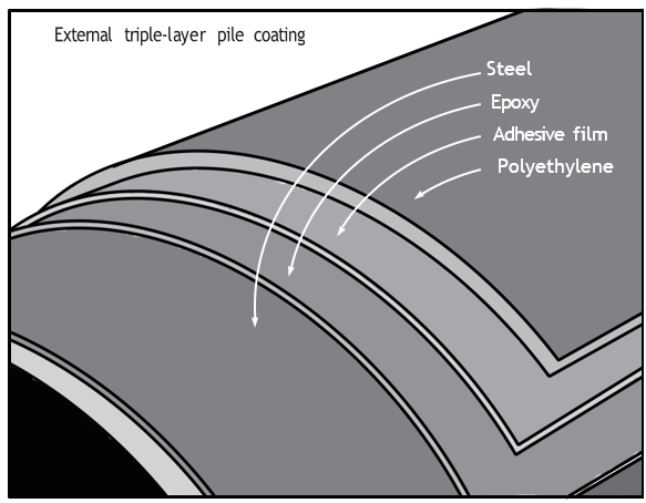
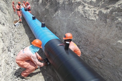
Pipe Coating Types and Methods
Liquid Coatings
Liquid coatings have the following uses and advantages:
- Ideal for pipeline rehabilitation and coating repairs
- Suitable for field applications such as large recoating projects or short pipe sections
- Available in formulations that are 100% solids with no volatile organic compounds (VOCs)
- Often do not require a primer and allow for high-build single-coat application
- Can be applied with either spray or brush
The selection of pipe coatings is usually done by project design engineers.
Pipe coatings are applied to piping to protect the pipe from the degrading effects of the environment they are installed in. The types of protective coatings and the materials that make up the composition of the coating depend on the type of pipe and the damage that the pipe is going to be subject to. The methods used when applying these coatings is dependent on the manufacturer’s application instructions and the type of pipe material it is applied to.
Mastic elastomeric coatings (soils saturated with oil and gasoline) may be used as a general-purpose coating for underground corrosion protection of all fabricated steel products, such as pipes, tanks, conduits, cylinder casings, and structural steel.
Other Mastic Coatings
Coal-tar-based epoxy combines the superior moisture resistance of coal tar with the excellent chemical and abrasion resistance of epoxy. Environments include chemical plants, flood gates, locks and dams, sewage plants, bridge and piling structures, and pipelines. Coal-tar-based is also used for immersion service and in atmospheric conditions where abrasion and chemical resistance are needed. It is used in industries such as sewage and water treatment, chemical processing, marine, offshore exploration, oil and gas distribution, and public utilities.
Rubberized mastic is a cold-applied coating with high electrical resistivity designed to protect underground steel pipes, tanks and other structures against corrosion.
Tape and Wrap Coatings
The external surfaces of steel pipe can be protected from corrosion by external pipe coatings. Pipe coatings include both liquid and powder coatings, pipe wraps and tapes, and can be applied at the factory or on the job. Factory-applied coatings are usually more reliable since they’re applied in a controlled environment.
Geotextile Pipe Protection
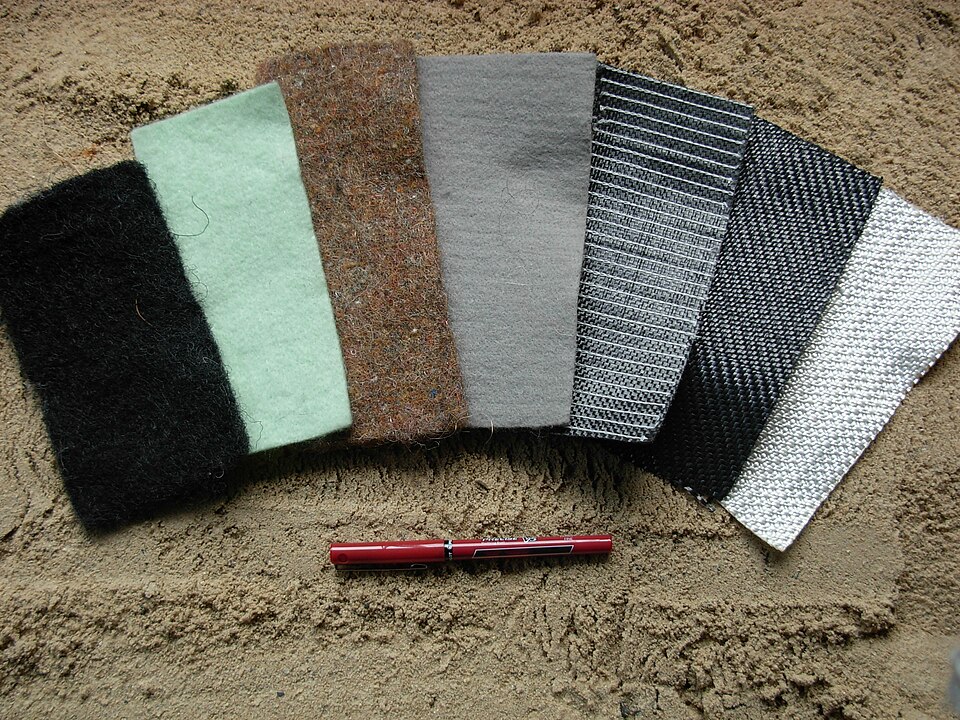
Geotextile sacrificial wrap provides protection for surface coating during backfilling operations and is often placed around the pipe prior to placement in the trench.
Pipe Casing
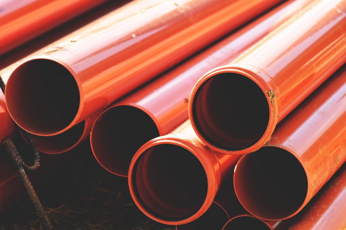
Pipe casing is a method to protect a pipe by encasing the transporting pipe within a larger pipe. Pipeline casing filler is a petrolatum-based corrosion-preventative compound used to fill the void between the transporting and external pipes. It prevents corrosion by displacing water that is present in the casing and by preventing water from re-entering the casing.
Rock Guards
Rock guards are used to protect pipe protective coating from damage from soils with rocky backfill. The product is available in rolls or pads for varying diameters of pipe.
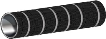
Transmission Sleeve
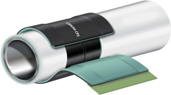
A transmission sleeve is used for field application at a joint in a pipe with existing pipe protection. (For example, an underground welded gas line.) The transmission type sleeve system provides corrosion protection and bonding on pipelines ranging from operating temperatures up to specified temperatures. They are designed to bond to the existing pipe protection.
Freeze Protection
Exposure of piping systems to freezing conditions will cause water and similar low freezing point fluids to freeze. The expansion of the fluid (water) as it freezes can rupture the pipe. When the water thaws the resulting water damage can be extensive.
Several methods can prevent freezing damage, including:
- Installing piping within a heated structure
- Applying insulation or enclosing the pipe (e.g., boxing, tenting, spray foam)
- Installing piping on the heated side of building insulation
- Draining or blowing out the system during cold weather
- Adding antifreeze solution
- Using hot boxes
- Installing heat trace systems
- For buried piping, installing the piping below the frost line or insulating and heat tracing
- Using constant circulation
The easiest way to prevent a piping system from freezing is to install the system within a heated structure. Building standards will often not allow potable water systems to be installed in exterior walls, especially in regions subject to freezing conditions without specific freeze protection. Fire sprinkler systems installed in areas subject to freezing may be designed to be a dry pipe system, for example, parking garages and warehouses. The use of low-point drains are examples of frost-protection measures. Constructing an insulated box around piping or installing the pipe on the warm side of the building insulation is an acceptable way to insulate piping.
Piping installed in attic spaces, such as the case with residential fire systems, must be protected from freezing. Fire codes have standards on the methods of application of insulation in residential fire sprinkler systems.
Irrigation systems are often designed with compressed air blow out connections and low point drains. Irrigation systems are usually winterized by simply shutting down the systems and draining for the winter season.
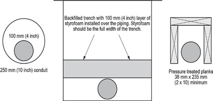
Underground piping that can’t be installed below the local frost line can’t be insulated using materials that would crush under the weight of the compacted fill. Because of this, you might need to install a frost box. A frost box is the term given to one of three accepted assemblies (see the accompanying diagram):
- An inverted U made of treated wood planks that is installed over the pipe and that maintains an air space between the pipe and planks. Freezing time would be longer due to the absence of physical contact between the pipe and the planks.
- A pipe installed inside a much larger pipe. The outer pipe reduces contact between the pipe and the frozen earth around it.
- High-density styrofoam used to separate the pipe and the fill above it. This method requires very high compaction of the fill around the pipe, and the Styrofoam must be of dense construction.
As long as water is moving, it is unlikely to freeze. Leaving a faucet dribbling to a drain can sometimes be effective to prevent freezing, but it wastes a lot of water. This adds cost to owners on a metered system and adds volume to a private septic or a municipal treatment system.
Using a pump to keep water circulating within a closed system, much the same as in a domestic hot water recirculation system, can effectively reduce the threat of freezing and prevent wasting water. Water at the end of the piping run is pumped back to its starting point through a separate pipeline. It is important that these systems are sized correctly to avoid unnecessary erosion of the pipe walls from excessive flow velocities.
Piping Materials and Frost Protection Considerations
Different piping materials respond differently to freezing conditions, which has important implications for system design, installation, and maintenance in cold climates.
Compared to copper piping, PVC plastic pipe generally takes longer to freeze due to its lower thermal conductivity. However, once freezing occurs, PVC is more rigid and brittle, causing it to burst at a lower internal pressure when ice expands inside the pipe. This makes PVC particularly vulnerable to sudden failure during freeze–thaw cycles, especially in unheated spaces or exterior installations.
Polyethylene (PE) and cross-linked polyethylene (PEX) piping offer greater resistance to freeze-related damage. These materials have a higher degree of flexibility than copper, allowing them to expand slightly as water freezes. This flexibility enables PE and PEX pipes to better absorb the internal pressure caused by ice formation, often preventing the pipe from bursting. In many cases, these pipes can return to their original shape once thawed, provided the freezing was not prolonged or extreme.
Copper pipe, while strong and durable under normal conditions, is relatively rigid and has little ability to expand. When water freezes inside a copper pipe, the expanding ice can generate significant pressure, leading to splitting or rupturing of the pipe, particularly at fittings or soldered joints.
Because of these material characteristics, frost protection measures—such as proper insulation, heat tracing, adequate pipe sizing, and strategic routing away from exterior walls—are critical regardless of the piping material used. However, material selection can play a significant role in reducing the likelihood and severity of freeze damage, especially in residential and light commercial applications.
Applying Freeze Protection
When pipe is installed where it is subject to freezing, the first solution is to apply pipe insulation. The goal is to maintain the temperature of the pipe and contents above the freezing point.
There are many types of insulation pipe wraps available. In many cases, batt fibreglass insulation is simply packed around the pipe in question. Pipe is often boxed in, and insulation is placed in the box surrounding the pipe. Often insulation is not protected from moisture and the environment. Water-soaked insulation does not provide good insulation.
In-ground valve and meter boxes are installed with some method to prevent freezing. Installation of piping below the frost level is a good solution. Where this is not possible, the piping can be covered with light-weight material with insulation qualities. Sawdust and wood chips and shavings can work in dry environments for limited amounts of time before needing to be replaced.
The application of freeze protection requires consideration of the type of insulation and its thickness. It’s difficult to know how much insulation is required. How cold will an unheated crawl space, attic, or outside wall get? How long is the ambient temperature going to stay below freezing? Will additional heat trace cable be required? If the pipe freezes, the resulting damages can be costly. Given this, it’s better to be safe than sorry.
Factors affecting heat loss include:
- Thickness of installation
- Ambient temperature
- The size of pipe and the amount of residual heat
- Wind speed (for pipes exposed to wind)
Types of pipe insulation include:
- Flexible closed-cell polyethylene
- Fibreglass
- Mineral wool
- Natural insulation
- Foam
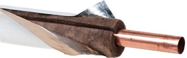
Flexible closed-cell polyethylene or elastomeric insulation are often used for insulating plumbing, both residential and commercial. These lines are found in crawl spaces, walls, attics, parking garages, and unheated warehouses. The closed cell has excellent range of properties, including low thermal conductivity, water vapour permeability, and ease of installation. There is no need for additional water vapour barrier.
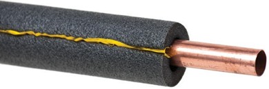
Styrofoam Insulation
Styrofoam insulation is a rigid, closed-cell foam pipe insulation. This insulation has a dense, compact structure ensuring resistance to water, water vapour, and wet freeze-thaw cycling.
Using insulation by itself may be satisfactory in climates where freezing temperatures are rare and for short periods of time only. Where climate temperatures drop below freezing and last for extended periods of time, insulation and heat tracing is recommended.
Heat Trace
Heat tracing protects pipe from freezing by applying a heat-producing source, such as an electrical heat trace cable. The effectiveness of such heat trace or cable depends on correct selection and proper installation.
Heating cable systems can be controlled either manually or by thermostatic control. Self-regulating and all heating cables should be Underwriters Laboratory (UL) Listed, Canadian Standards Approval (CSA) certified, or Factory Mutual (FM) approved for their use. The most common thickness for heat trace is [latex]\frac{1}{4} \text{"}[/latex], and the insulation’s inside diameter must be sized properly to fit over both the pipe and the tape. This is done to ensure the insulation seam will close tight and stay tight.
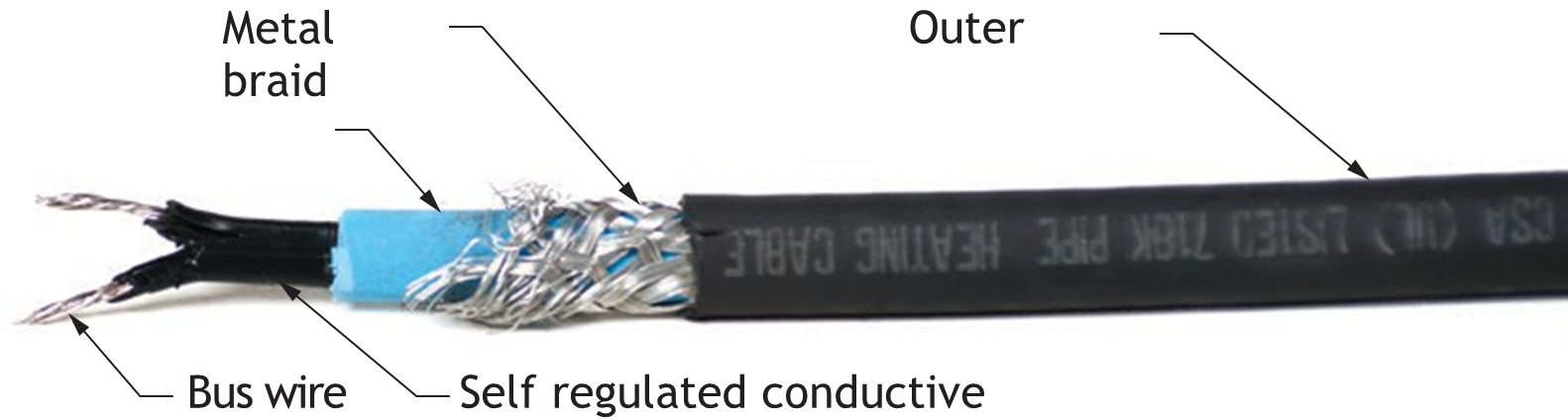
Heat trace frost protection cable is constructed of several layers. The inner layer of the cable contains two conductor wires that supply electrical power to the heat tape. Surrounding the two wires is a special polymer that generates heat when electrical current flows through it.
Some manufacturers supply heat trace cable in coils that may be cut to the exact length needed for a job. Cable connectors and end seals are supplied to terminate the cut ends.
Heat trace cable is also supplied in specific lengths. These pre-cut lengths should not be further cut unless specifically allowed by the manufacturer.
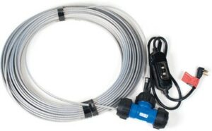
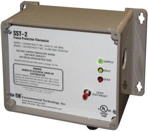
Thermostats
Heat tracing systems may be controlled either manually or through thermostatic control. Manual control requires the operator to turn the power to the heating cable on or off as needed, relying on judgment and monitoring of ambient conditions.
Thermostatic control uses a temperature-sensing switch to automatically energize or de-energize the heating cable at preset temperatures. This method provides more consistent freeze protection and improved energy efficiency by ensuring the system operates only when required.
Aluminum Foil Tape
When required, aluminum foil tape is applied to the pipe under the heat trace. This will provide better conductivity to the pipe, particularly for plastic piping. Aluminum tape can also be used to attach the heat trace tight to the pipe and keep insulation from getting under the heat trace.
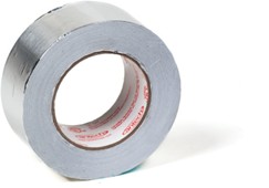
Heat trace cable is available thermostatically controlled or self-regulating. Self-regulating cable consists of a polymer in the cable that has a resistance that changes with the temperature. For example, one manufacturer states that their cable uses about 3.5 watts per foot at 4.4°C (40°F). At –17.7°C (0°F), the power usage increases to about 5 watts per foot. The heat trace cable is simply plugged in or turned on for the winter season and unplugged or turned off at the end of the cold season.
Heat Trace Safety
The following are some considerations for heat trace safety:
- Do not use heat trace cables below ground unless specifically approved for such use.
- Heat trace should be plugged into a grounded electrical receptacle in a dry area.
- Ground fault interruption may be required (consult electrical codes).
- Do not cut or splice heat trace cable unless specifically approved by the manufacturer and electrical codes.
- Heat trace should not be enclosed in walls, ceilings or floors.
- Heat trace must be visible for inspection (under pipe insulation is permitted if specified by the manufacturer’s installation instructions).
Heat Trace Selection
Factors to consider when selecting and installing a heat trace cable include:
- Pipe diameter
- Pipe length
- Minimum ambient temperature (worst-case scenario)
- Temperature rating of the fluid being transported
- Manufacturer’s sizing tables
Note: A typical maintained temperature of 5°C (40°F) is acceptable. This maintained temperature is used to determine the maximum length of the tracer circuit and the size of the electrical breaker.
Recommended Heat Trace Installation Practices
- The pipe and heat trace cable should extend into the building approximately 300 mm as the pipe enters the building and well below the frost line if the pipe exits or enters the ground.
- For short branches run off a main, you can double-trace (down and back) to eliminate the need for splicing.
- Avoid running heat trace cables through open air from pipe to pipe. Use a conduit extension to protect the cable.
- Select the cable wattage conservatively, allowing a slightly higher wattage output, per foot of cable, than required.
- Insulate all heat sinks in the heat tracing system. Allow sufficient cable to trace additional heat sinks.
- Avoid wrapping heat trace cable around a valve so the valve cannot be easily removed or repaired.
- The better insulation value of the pipe insulation, the less wattage required and the longer the runs.
- Larger pipe may require more than one heat trace cable.
- Place aluminum foil tape over the heat trace cable before applying spray on insulation—this will improve heat transfer to the pipe.
- Avoid contacting heat trace cable with steam from steam cleaning operations—the high temperature can damage the cable.
Electrical Considerations
- Design the heat tracing system using the most commonly expected start-up temperature. Maintaining the higher start-up temperature uses less power and allows longer heat trace circuits and smaller circuit breakers. Breaker tripping may occur if the heating system starts at a lower temperature than it was designed for.
- The maximum lengths and breaker should be in conformance with the manufacturer’s specifications and Electrical Code requirements.
- All heating cable systems require ground fault protection as required by the National and Canadian Electrical Code.
For the required wattage given the pipe diameter, the ambient temperature, and the amount of insulation, use the tables provided by the heat trace manufacturer.
Methods Used to Install Heat Trace
Methods used to attach heat trace to pipe include flexible nylon straps and flexible heat trace tape. When attaching heat trace, ensure that the tape or strapping is rated for the temperature of the piping when in use. Do not use metal strapping or tie wire. It’s important that the heat trace makes positive continual contact with the pipe surface to provide the best results.
Temporary Attachment
Starting at the end of the circuit and working back towards the power source, attach the heat trace temporarily. Allow extra tracer cable for final attachment to valves, flanges, elbows, and at pipe supports. Also allow extra cable for the power connection and for any splicing that may be required. Pipe supports can act as a heat sink, so on sizes over 2″ in diameter, extra heat trace may be required.
Permanent Attachment of Heat Trace
For instructions applying to large diameter industrial piping or residential application, see the manufacturers’ instruction
Ultraviolet Light (Sunlight) Protection
When thinking about UV protection, there are different considerations for different types of pipe and tubing.
ABS Pipe Protection
ABS piping should not be exposed to direct sunlight. An exception is a vent pipe passing through a roof. Vent piping exposed to sunlight must be protected by water-based synthetic latex paints.
Adequate support must be provided where ABS piping is exposed to wind, snow, and ice loading.
Piping passing through wood studs or plates must be protected from puncture by steel nail plates of not less than 18-gauge.
PVC Pipe Protection
PVC does not readily degrade when exposed to sunlight due to natural UV inhibitors present in the material. Short-term exposure of PVC to sunlight during construction is typically not a problem. PVC piping installed outdoors can be painted with a light coloured water-based acrylic or latex paint that is chemically compatible with PVC.
PEX Pipe Protection
PEX tubing is not intended for use outdoors. The tubing must be stored and used in a concealed environment. Some PEX manufacturers produce PEX with varying resistances to ultraviolet light. PEX tubing should not be exposed to ultraviolet light for extended periods of time. PEX tubing can handle ultraviolet light during the installation period; however, you should always consult the manufacturer’s specifications.
Note: Plastic piping should be protected from contact with concrete form release oils and foundation emulsions.
Fibreglass Pipe Protection
The effect of ultraviolet light on fibreglass pipe is limited to surface discolouration. Fibreglass pipe degradation is limited to the outer 0.005–0.01″ of the pipe. You may protect fibreglass pipe from the ultraviolet rays by painting with a heavily pigmented industrial coating it or by coating with an ultraviolet absorbing agent.
Pipe Condensation Protection
Pipes that operate below the ambient temperature of the surrounding air are subject to condensation. The moisture in the surrounding air condenses on the cold pipe surface. This accumulation of moisture may contribute to the corrosion of the pipe and/or its support. Moisture accumulation can contribute to damages to the surrounding building structure. Mould and bacteria growth can cause visual damage or promote rot in wood structures.
Typical examples of piping subject to condensation include:
- Cold water piping
- Storm and rain water drainage piping leading from roof areas and passing through the heated structure
- Piping installed in cold storage facilities or freezers
Damage caused by this condensation may include:
- Staining of building surfaces
- Mildew and bacterial growth
- Decay of structural components
- Promotion of electrolysis causing damage to pipe and supports
- Oxidation of exterior pipe walls
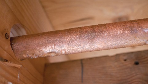
Methods used to prevent condensation include:
- Pipe insulation
- Reduction of moisture content through the use of heat recovery ventilation systems or dehumidifiers
- Use of a vapour barrier to eliminate air infiltration through openings surrounding the pipe
Physical and Mechanical Pipe Damage Protection
There are different sources of damage to pipes, requiring protection.
Steel piping installed parallel to or through wood frame members rarely needs protection from punctures by nails or screws. Plastic and copper tubing, however, is not as robust and therefore needs to be protected from this threat. Protective prescriptions for gas piping or tubing are laid out in the CSA B149.1 Code for the installation of natural gas and propane systems, but protection of water lines is not really addressed quite as specifically in the plumbing codes. Following the gas code references for tubing protection should ensure adequate protection for water pipe installations.
When the tube is installed within joist spaces and parallel to the joists, keep the tube face at least 1 [latex]\frac{3}{4} \text{"}[/latex] (43 mm) above the face of the joist to prevent contact with drywall nails or screws. When run through holes in joists or studs, maintain that same 1 [latex]\frac{3}{4} \text{"}[/latex] (43 mm) distance between the face of the stud or joist and the edge of the tube. If that minimum separation cannot be maintained, use protective plates or sleeve.
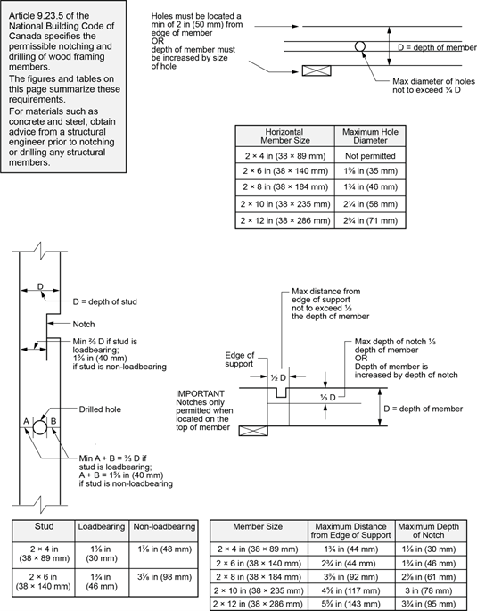
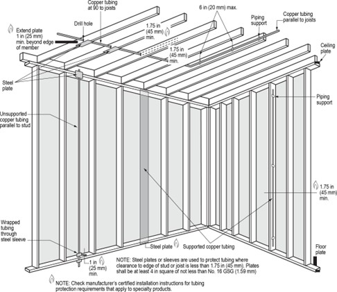
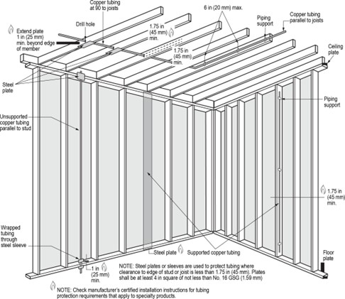
A small diameter pipe run through oversized holes drilled through the centre of 2 x 6 studs usually maintains that minimum separation. Oversized holes allow the pipe to deflect if hit. In drilling the holes, however, make sure to not compromise the structural integrity of the stud. If running piping through a 2 x 4 stud wall, the minimum separation usually cannot be met, so it would require that heavy gauge steel protection plates be attached to the stud face. This method usually causes the drywall to bulge outward at that point, so an alternative method would be to run the pipe or tube through short sleeves of electrical metallic tubing (EMT) that are larger than the water line. The sleeves are meant to be fitted tightly into the drilled holes so they can’t fall out, and the pipe or tube must be wrapped with a dielectric such as electrician’s tape to prevent galvanic corrosion between the pipe and the pipe sleeves. Also make sure to ream the cut ends of the pipe sleeves to prevent abrasion of the tubing running through them.
Expansion and Contraction of Piping
Pipe expansion and contraction occurs when the piping is subject to temperature changes. The temperature changes can be a result of internal fluid temperature or external temperature caused by the surrounding environment. When piping heats up, it will expand. When piping cools down, it will contract. Continued uncontrolled expansion and contraction of piping can result in damage or failure of the pipe or the components of the piping system.
Damage to the building structure can occur when expanded piping has not been controlled. Uncontrolled expansion and contraction stresses applied to connected appliances and equipment can result in damage. It is your responsibility to recognize the expansion and contraction issues and apply installation practices to control it. Providing proper clearances from building structural components and the use of piping fittings and piping design layout can effectively limit and control the forces of expansion and contraction.
Expansion Control for Metallic Piping
Manufactured Expansion Joints
Manufactured expansion joints are used to protect metallic piping. There are different kinds.
A single bellows expansion joint is simply a bellows element with end connections. It will deflect in any direction—to keep the pipe and bellows in line, the joint is controlled with pipe guides or anchors.
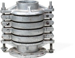
Slip-Type Expansion Joints
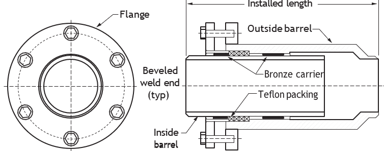
Slip-type expansion joints are used when the primary problem is large axial movement. The design is basically an inside and outside barrel (sleeve), with a mechanical seal between them that slides back and forth as the pipe expands and contracts.
Installation Practices for Manufactured Expansion Joints
The following summarizes installation practices for manufactured expansion joints.
- Follow the manufacturer’s precautions.
- Inspect for damage during shipment. i.e., dents, broken hardware, water marks on carton, etc.
- Store in clean dry area where it will not be exposed to heavy traffic or damaging environment.
- Use only designated lifting lugs.
- Make the piping systems fit the expansion joint, rather than the other way around.
- Leave one flange loose until the expansion joint has been fitted into position. Make necessary adjustment of loose flange before welding.
- Install joint with arrow pointing in the direction of flow.
- Install single Van Stone liners, pointing in the direction of flow. Be sure to install a gasket between the mating flange and liner.
- With telescoping Van Stone liners, install the smallest ID liner pointing in the direction of flow.
- Remove all shipping devices after the installation is complete and before any pressure test of the fully installed system.
- Remove any foreign material that may have become lodged between the convolutions.
- Refer to appropriate standards for proper guide spacing and anchor recommendations.
- Do not drop or strike the delivery carton.
- Do not remove shipping bars until installation is complete.
- Do not remove any moisture-absorbing desiccant bags or protective coatings until ready for installation.
- Do not use hanger lugs as lifting lugs without approval of manufacturer.
- Do not use chains or any lifting device directly on the bellows or bellows cover.
- Do not allow weld splatter to hit unprotected bellows. Protect with wet chloride-free insulation.
- Do not use cleaning agents that contain chlorides.
- Do not use steel wool or wire brushes on bellows.
- Do not force-rotate one end of an expansion joint for alignment of bolt holes. Ordinary bellows are not capable of absorbing torque.
- Do not hydrostatic pressure-test or evacuate the system before installation of all pipe guides and anchors. Pipe hangers are not adequate guides.
- Do not exceed a pressure test of 1.5 times the rated working pressure of the expansion joint.
Bellows Misalignment
During the installation of the piping systems, the accuracy of the location of equipment, pipe supports, structure, and the piping itself is often not perfect. The expansion joint is usually far more easily deflected than any of these other components. The use of the expansion joint to correct imperfections in piping alignment is not recommended. The expansion joints will arrive from the factory with rigid restraints that maintain their length and ends in the position and dimensions of the specification. Do not remove prior to, or during, installation.
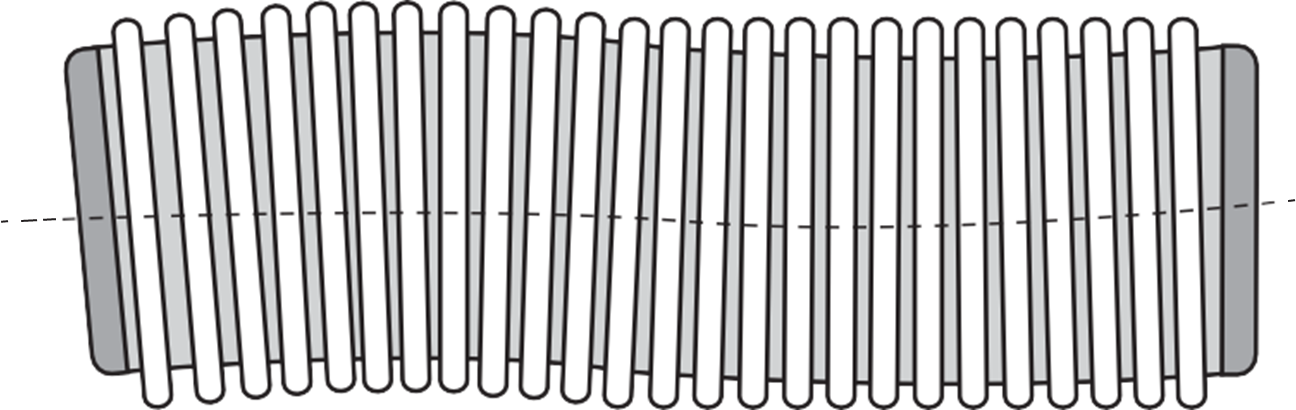
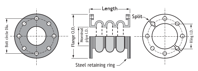
Rubber Expansion Joint
A rubber expansion joint, illustrated:
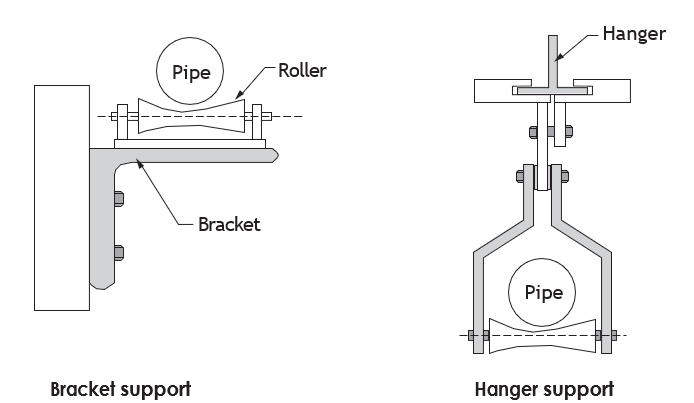
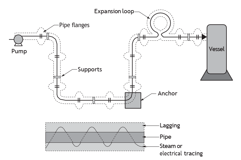
Roller Hangers, Expansion Loops, and Supports
The following illustrations show common roller hangers, expansions loops and supports.
Pipe Guides
Pipe guides ensure that the thermal expansion of the pipeline is properly directed into the expansion joint and to prevent buckling of the line. Additional guides located adjacent to the expansion joint are necessary because of the inherent flexibility of the bellows and the compressive loading on the pipe caused by the pressure thrust of the expansion joint.
The first guide must be located within a distance of four pipe diameters from the expansion joint, and the second guide within fourteen pipe diameters of the first guide. Additional guides should be located in accordance with the manufacturer’s guidelines.
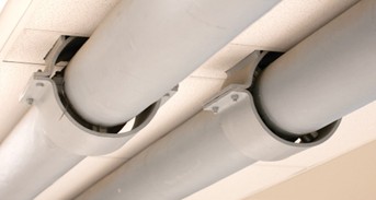
In Figure 21, below, two pipe guides allow pipe to move and are kept in line by the large guide sleeve. Sections bolted to pipe keep the pipe centred in the guide sleeve. The guide sleeves are anchored solidly to the building structure.
Pipe Guide and Pipe Anchor Placement
Proper pipe guiding is essential to an installation of expansion joints or pipe expansion loops. Properly located pipe guides and anchors keep the pipe in line and reduce or eliminate excessive misaligning forces on the expansion joint.
Guides normally permit axial movement of the pipe, while restraining both lateral and angular movement. Pipe guides support the pipe and guide the pipe expansion.
The location and number of pipe guides and anchors is dependent upon:
- Proximity of the expansion joint to an anchor
- Diameter of the pipe
- Length of the pipe run

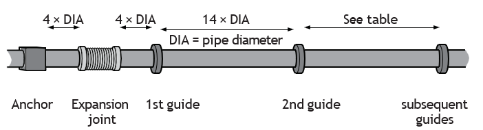
Figure 25 Location of pipe guides and anchors on straight pipe lengths (BC Industry Training Authority, 2019). CC BY-NC-SA 4.0
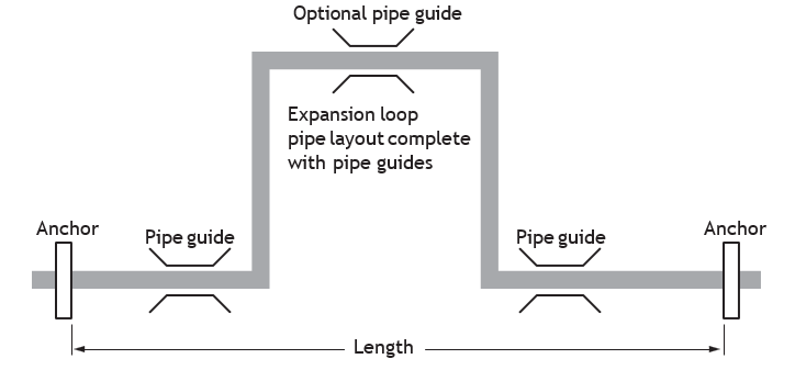
Figure 23 shows the placement of pipe guides and anchors for an expansion loop.
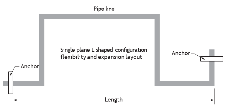
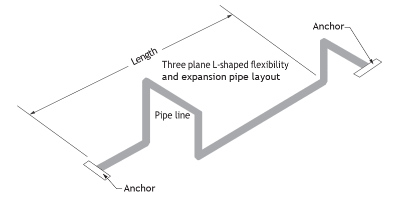
Offsets and Changes of Direction to Maintain Piping System Flexibility
Piping flexibility is probably the least understood function of piping design. Although not often thought about in residential applications, it’s an important application in larger commercial applications, industrial, and process piping. It’s preferable to provide adequate flexibility in piping systems by using elbows to create additional changes of directions in the piping layout. Where space is limited or cost considerations apply, manufactured expansion joints may be used. A good expansion design will provide the maximum flexibility using a minimum number of fittings.
As with any pipe expansion provisions, the use of pipe guides to keep the pipe in line and pipe anchors to direct the expansion is required. An anchor placed near the centre of the run will direct expansion by forcing 50% of the expansion to either side of and away from the anchor point. Remember that pipe guides are used to keep the pipe in alignment.
The design of pipe expansion provisions is normally the work of the design engineer. However, as an installer, it’s useful to recognize the basic piping design configurations used to provide for pipe flexibility and expansion movement.
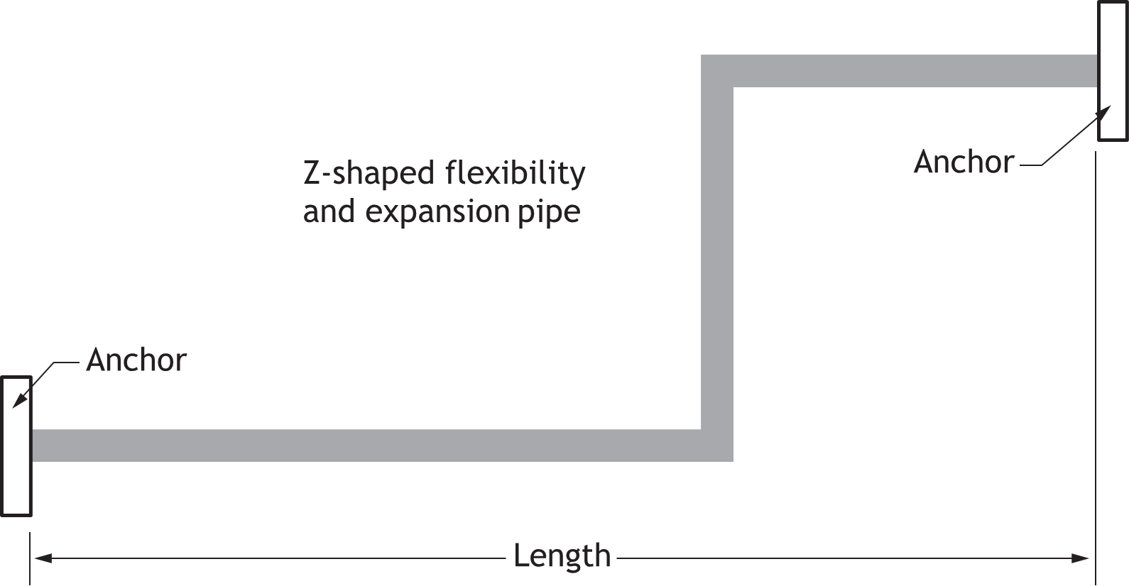
Figures 24–27 illustrate the various piping arrangements used to provide flexibility and accommodate expansion in industrial and process piping applications.
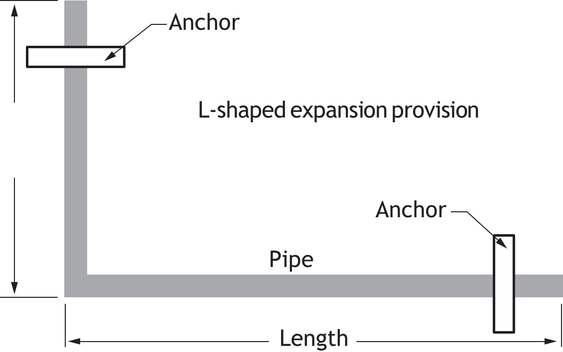
Design engineers calculate the flexibility and expansion required. They can then design the piping layout and the required dimensions of L and H to accommodate system flexibility and expansion.
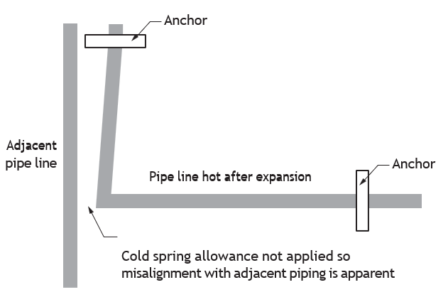
Cold Spring in Piping
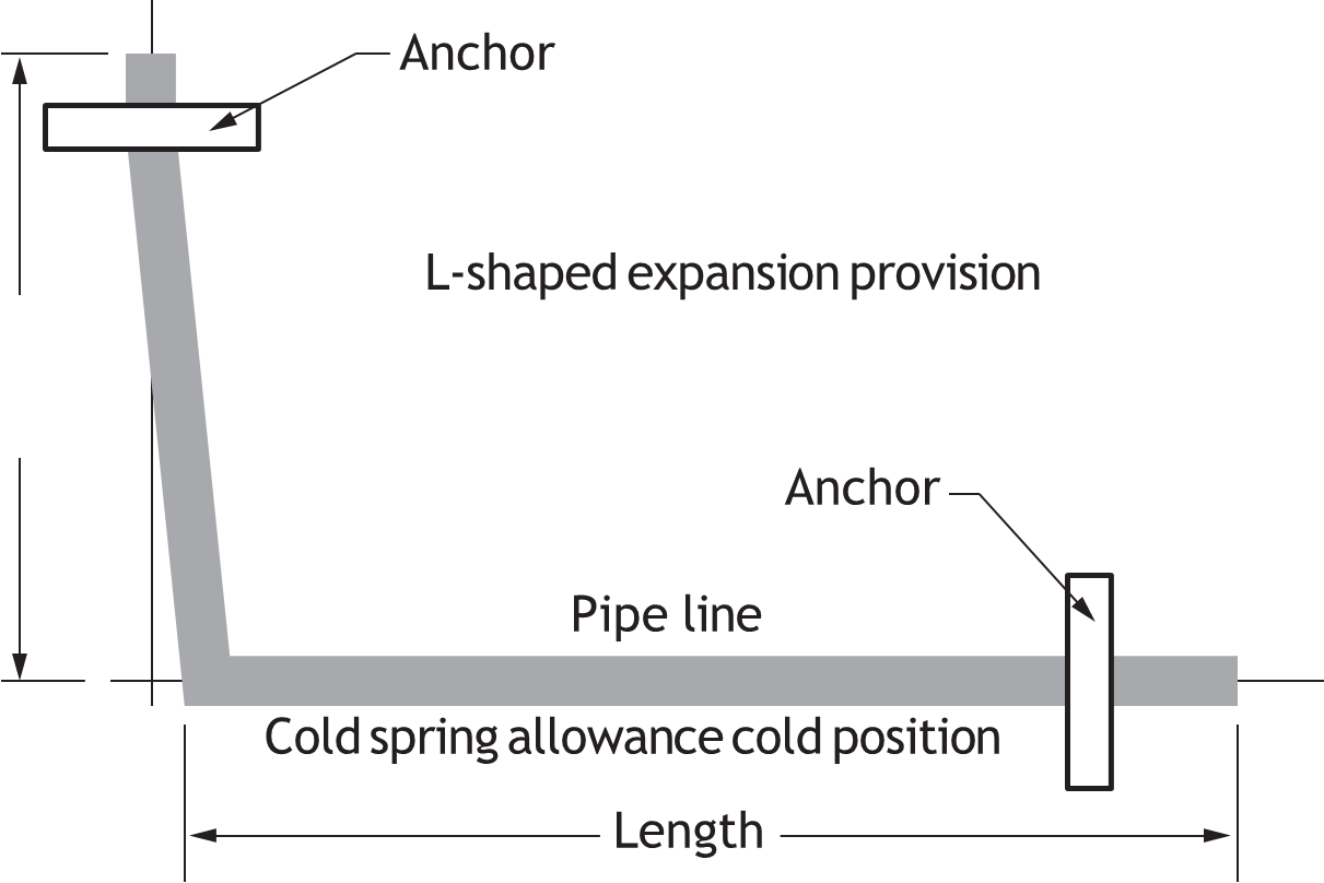
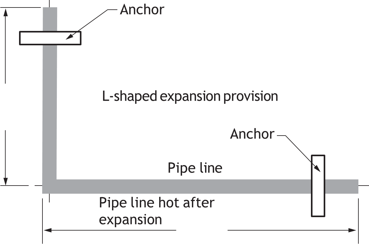
Cold spring is the allowance made during installation of the piping to accommodate for the final pipe position after expansion has occurred. Cold spring is applied to piping systems for these basic reasons:
- When required by a design engineer’s detailed stress analysis
- To maintain adequate pipe spacing in rack, parallel pipe installations
- To prevent visual misalignment with adjacent piping or structure Figures 28–30 show the theory behind cold spring:
Piping Fittings that Provide Provisions for Expansion Within Piping Systems
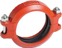
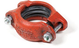
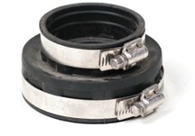
Various types of plumbing and piping fittings that have flexible joints can reduce the stresses of pipe expansion. Fittings designed for joining grooved fittings and pipe use flexible composite rubber seals that, when clamped to the pipe, provide some degree of movement. Typical brand names include Victaulic, Groove Lock, and Press Fit.
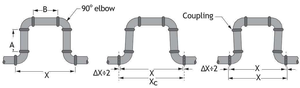
Flexible Mechanical and Grooved Type Joints
Flexible mechanical joints can be used in expansion loops without inducing stress in pipes, elbow, or joints. These flexible couplings and fittings have the ability to allow thermal expansion and contraction to be absorbed at elbows and fittings. Pipe configurations can be reduced in size when using these types of fittings (Figure 31).
Swing Joints and Spring Pieces
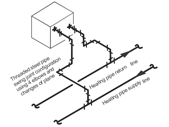
Swing joints are piping configuration that allow for flexibility, expansion and contraction. The piping configuration for a swing joint includes the use of a minimum of three elbows, as well as a change
in direction and plane. Swing joints are used when connecting equipment such as heat transfer units, gas utility meters, irrigation heads and so on. Swing joints can align piping to the attached equipment and ease the stresses and strains on the equipment connection point.
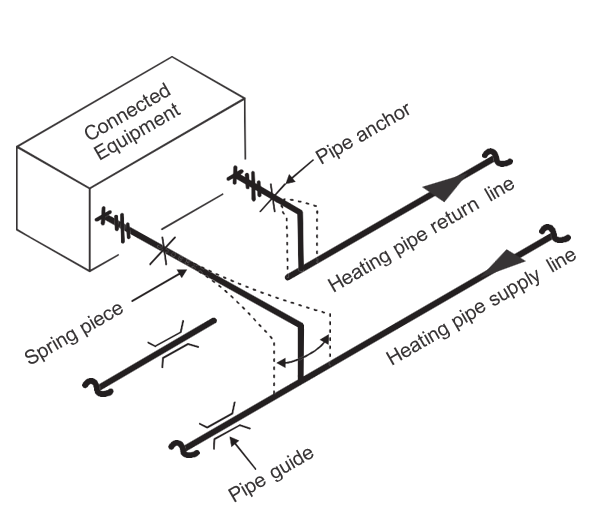
Spring Pieces
Spring pieces are section of pipe that, because of their size, length and material, can flex, dispersing any forces and strain along their length. Anchors may be required to reduce stresses on connected equipment. Swing pieces can be applied when fitting joint methods that do not provide flexibility or movement, such as soldered, brazed, or welded fittings.
ABS and PVC Plastic Piping Expansion Protection
Expansion within ABS and PVC piping systems is an important issue. Hot and cold wastewater flowing in plastic piping causes the plastic pipe to expand and contract. In residential wood-frame construction, there is often shrinkage of the wood-frame itself. This shrinkage will cause stress on the ABS pipe if it has been rigidly attached to the structure.
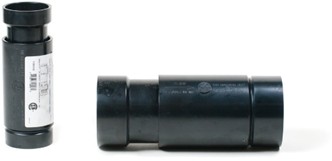
ABS DWV and PVC piping has a relatively high rate of expansion when exposed to heat. The linear expansion of ABS is approximately 13 mm ([latex]\frac{1}{2} \text{"}[/latex]) for each 5°C (10°F) change for each 30 m of pipe (100′). ABS piping is often controlled by the naturally occurring piping offsets and changes of directions in a residential building. ABS expansion joints are typically applied in residential applications when a vertical ABS drainage pipe passes through two floor levels. Vertically installed expansion joints will also provide for naturally occurring shrinkage in wood-frame structures.
Failure to allow for expansion, contraction and shrinkage may result in:
- loss of pipe slope
- pipe bowing
- stress breakage of fittings
- noises caused by plastic piping rubbing against the building structure
Placing ABS drainage piping in walls other than living rooms, dining rooms, studies and video viewing rooms is a good practice.
Guidelines for Installation of ABS Drainage Waste and Vent Piping
Thermal expansion and contraction of plastic drain waste and vent systems must be taken into consideration. Thermal expansion and contraction may be controlled with several methods, including:
- installing expansion joints on vertical ABS drainage pipe
- installing structural penetrations (holes) so they are large enough to provide free movement of the pipe without binding
- providing adequate support without rigidly restraining piping at changes of direction
- designing appropriate changes in piping direction, or offsetting the pipe
PVC Expansion Joint Installation
The travel of expansion joints is typically up to approximately 75 mm (3″). Set the expansion joint approximately mid-point of its full travel. Make sure that the expansion joint is anchored at one end and that the upper piping is guided to maintain straight alignment with the expansion joint. Failure to guide the pipe straight into the expansion joint can result in leakage of the joint. PVC expansion joints are typically placed close to the base of vertical stacks of drainage systems in residential applications. The seal is maintained by lubricated internal O-rings.
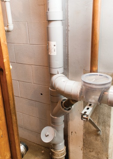
Dielectric and Cathodic Corrosion Protection
Electrochemical corrosion occurs when two dissimilar metals are in contact with each other in a moist environment. Although this can happen anywhere, it’s especially problematic for buried pipe. One metal becomes a cathode, and the other (usually the pipe) becomes an anode that corrodes and develops a leak. Cathodic protection reduces corrosion by forcing the pipe to act as the cathode. It is your responsibility to ensure that dielectric (cathodic) protection of pipe is used.
Cathodic Protection Applications
Cathodic protection systems are used to protect a wide range of metallic structures in various environments, including:
- Steel water or fuel pipelines
- Storage tanks such as home water heaters
- Steel pier piles, ship and boat hulls
- Offshore oil platforms
- Onshore oil well casings
- Metal reinforcement bars in concrete buildings and structures
Corrosion is the deterioration of metal pipe. Corrosion can be caused by an electrical reaction between the metallic pipe and its surroundings. As a result, the pipe deteriorates and may eventually leak. Although corrosion cannot be eliminated, it can be substantially reduced with cathodic protection.
All metals have a unique voltage stored within them. When two different metals such as copper and steel are connected together, the voltage difference between them will cause a DC electric current (electrons) to flow from the higher voltage to the lower.
Buried Piping Corrosion
Dissimilar soils create an environment that enhances corrosion in buried pipelines. The chemical makeup of the soil and the moisture present allow the soil to become a path for electrons to travel from the negatively charged area of a pipe (anode) to a positively charged area of the pipe (cathode). The movement of electrons away from the anode causes the pipe to corrode.
Definition of Terms
corrosion: The gradual destruction of material, usually metals, by chemical reaction with its environment. Typically, it refers to the electrochemical reaction with an oxidant such as oxygen.
electrochemical reaction: A reaction either caused or accompanied, by the passage of an electric current and involving the transfer of electrons between two substances.
electrode: An electrical conductor used to make contact with a part of a circuit. In an electrochemical cell, the electrode is referred to as either an anode or a cathode. Each electrode can be either the anode or the cathode depending on the current direction.
anode: A metal through which current flows. (In an electrochemical reaction, the anode is the metal that corrodes.)
sacrificial anode: A metallic anode intended to be dissolved to protect other metal components.
cathode: A metal from which current flows.
cathodic protection: A method used to control the corrosion of a metal surface by ensuring that the metal is the cathode in an electrochemical process. Normally, this process requires attaching or connecting the metal to a less-noble metal.
dielectric: A substance with a small amount of electrical conductivity.
disbondment: The separation of a protective coating from a pipe’s surface. Disbondment is accelerated when cathodic protection systems are operated with excessively polarized negative potentials, especially in systems operating at high temperatures.
rectifier: An electrical device that changes alternating current (AC) into direct current (DC). This current is then impressed on an underground metallic piping system to protect it against corrosion.
stray current: The portion of a current that flows over a path other than the intended path. There are two types of stray current: direct current (DC) and alternating current (AC). Stray currents found in the ground and in water promote corrosion of piping and metal components.
noble: Possessing outstanding qualities.
galvanic series: A list that indicates the relative stability of different metals and alloys in seawater, based on the measurement of corrosion potentials.
It’s important to note the rank of metals and alloys from least to most noble because when pairs of these metals are in contact with each other, the least noble one (i.e., the one highest on the list) will act as the anode, the metal that corrodes in an electrochemical reaction. Since magnesium and zinc are at the top of the list, they make very good sacrificial anodes.
In order for corrosion to occur, there must be four elements present:
- Electrolyte
- Anode
- Cathode
- A complete circuit
Corrosion will occur at the anode.
Methods of Cathodic Corrosion Protection
There are two basic methods of cathodic protection:
- Passive galvanic anode system
- Impressed current system
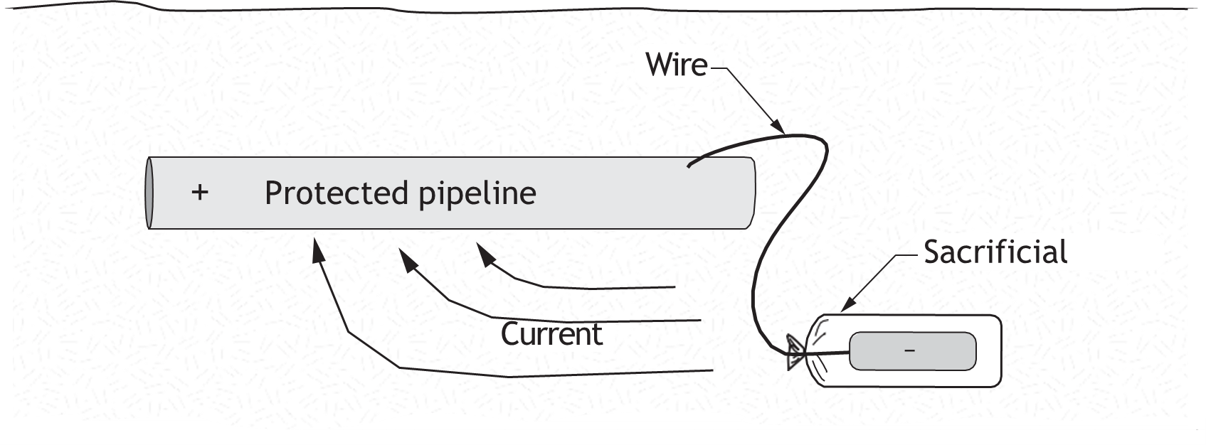
The simplest method of cathodic protection is to connect the protected metal with a sacrificial metal that acts as the anode in the electrochemical cell. The sacrificial metal corrodes instead of the protected metal.
Passive Galvanic Anode System
Anodes are usually installed near the pipe and connected to the pipe with an insulated conductor. They are sacrificed (corroded) instead of the pipe. Anodes are “sized” to meet the electrical current requirements of the soil. Anodes are made of materials such as magnesium (Mg), zinc (Zn), or aluminum (Al).
Galvanized (zinc) coatings used on pipe are durable in most environments and can provide a small localized degree of electrochemical corrosion protection. The zinc acts as the sacrificial anode, but only in the immediate location.
A proper corrosion protection system requires a sacrificial anode separate from the protected metal but connected by cables. This protects the entire system rather than just a localized section of pipe.
Galvanic Passive Anodes
The sacrificial anode consists of a bag containing either magnesium or zinc ingot and other chemicals and is connected by wire to an underground metal piping system. It functions as a battery that induces a direct current on the piping system to retard corrosion.
Impressed Current Systems
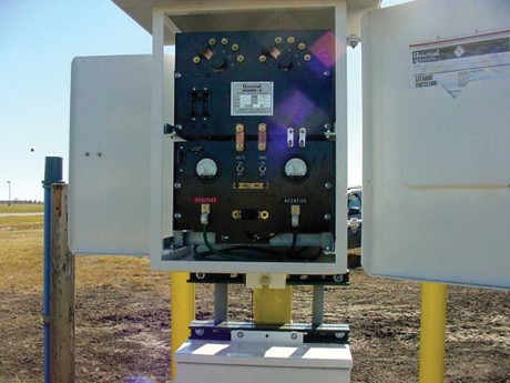
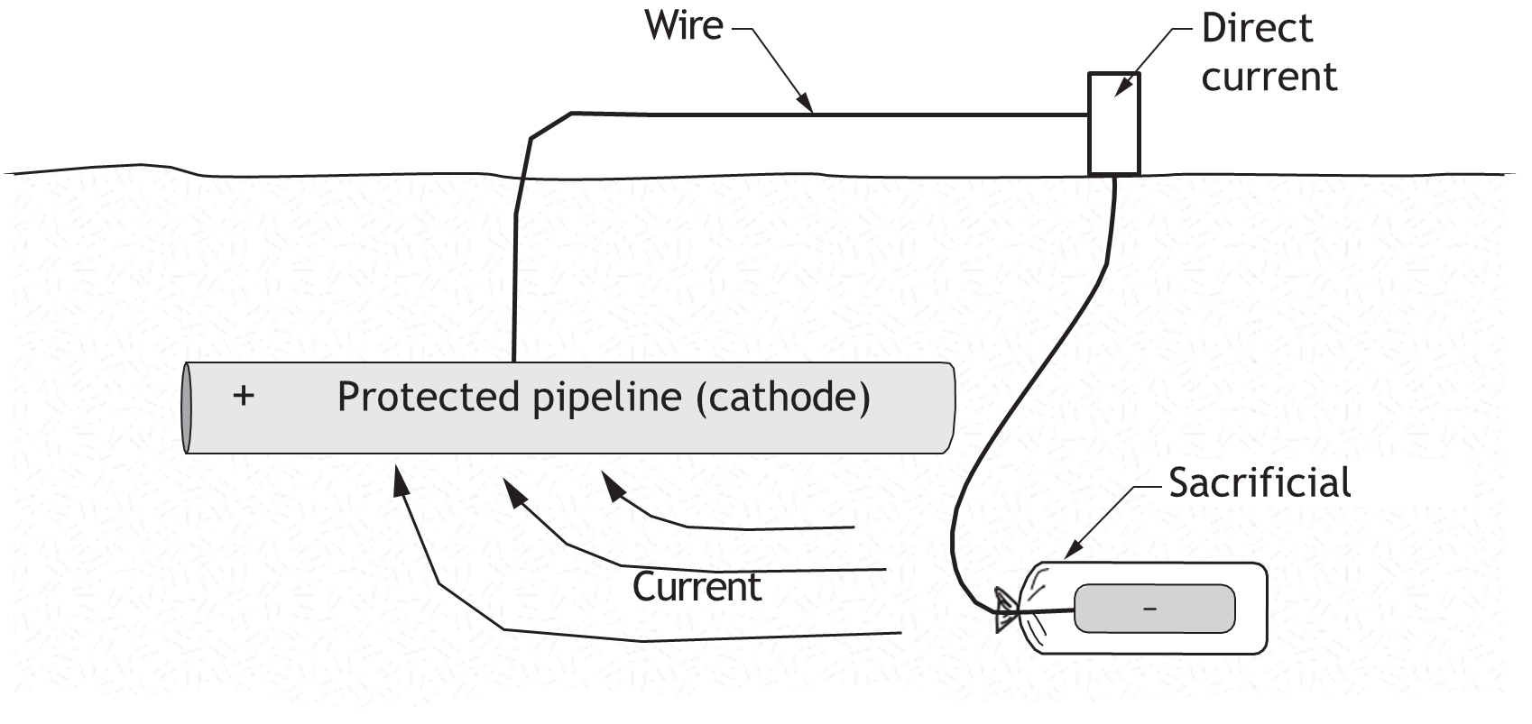
For structures where passive galvanic corrosion protection is inadequate (e.g., long pipelines), an external DC electrical power source is used to provide current. This direct current is induced onto the pipe by means of a rectifier.
These systems are normally used along transmission pipelines where there is less likelihood of interference with other pipelines. Anodes made of corrosion-resistant material such as graphite, high-silicon cast iron, lead-silver alloy, platinum, or scrap steel are used to disperse the electric current. The DC rectifier will typically have a DC output of between 10 and 50 amperes and 50 volts, depending on the system requirements.
Impressed Corrosion Protection Installation
The rectifier is connected by a cable to the anodes in the system. The other negative cable of the rectifier is connected to the pipeline.
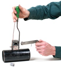
Anodes for cathodic protection system are often placed in a vertical hole or trench and then backfilled with conductive materials that improve the performance and life of the anodes. Installation factors also include the location and soil resistivity.
Figure 42 shows the equipment used to attach the anode wire to the pipe using the thermite weld method.
A flint striker gun must be used to ignite the starting powder. This will ignite the copper oxide flakes of the weld powder. The heat from the burning powder fuses the copper wire to the pipe. When the weld has cooled, the mold is removed and any exposed metal is coated with protective mastic.
Rectifier Safety
Rectifier safety is a concern to those who are responsible for rectifier installation, maintenance and repair. Rectifiers should be installed in compliance with appropriate electrical codes and the manufacturer’s instructions. Advances in rectifier design include safety features such as touch-safe features, advanced microprocessor technology, electronic fusing, and multiple access doors.
Stopping Galvanic Corrosion with Dielectric Fittings
Dielectric fittings are specialty fittings used to connect two dissimilar metals together. Without them, electrolysis can damage the weaker pipe.
Dielectric fittings are generally installed above ground to provide electrical isolation in piping systems. They can control stray electrical currents and cathodic protection current, and prevent the occurrence of dissimilar metal corrosion. Piping systems with a cathodic protection current should be regulated to follow a specific electrical path. The installation of dielectric unions is a method for electrically isolating cathodically protected piping systems.
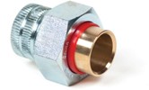

To prevent electrolytic corrosion in dissimilar piping connections, dielectric unions and fittings are used. The dielectric fitting prevents contact between the dissimilar metals interrupting the electric current that would otherwise cause corrosion.
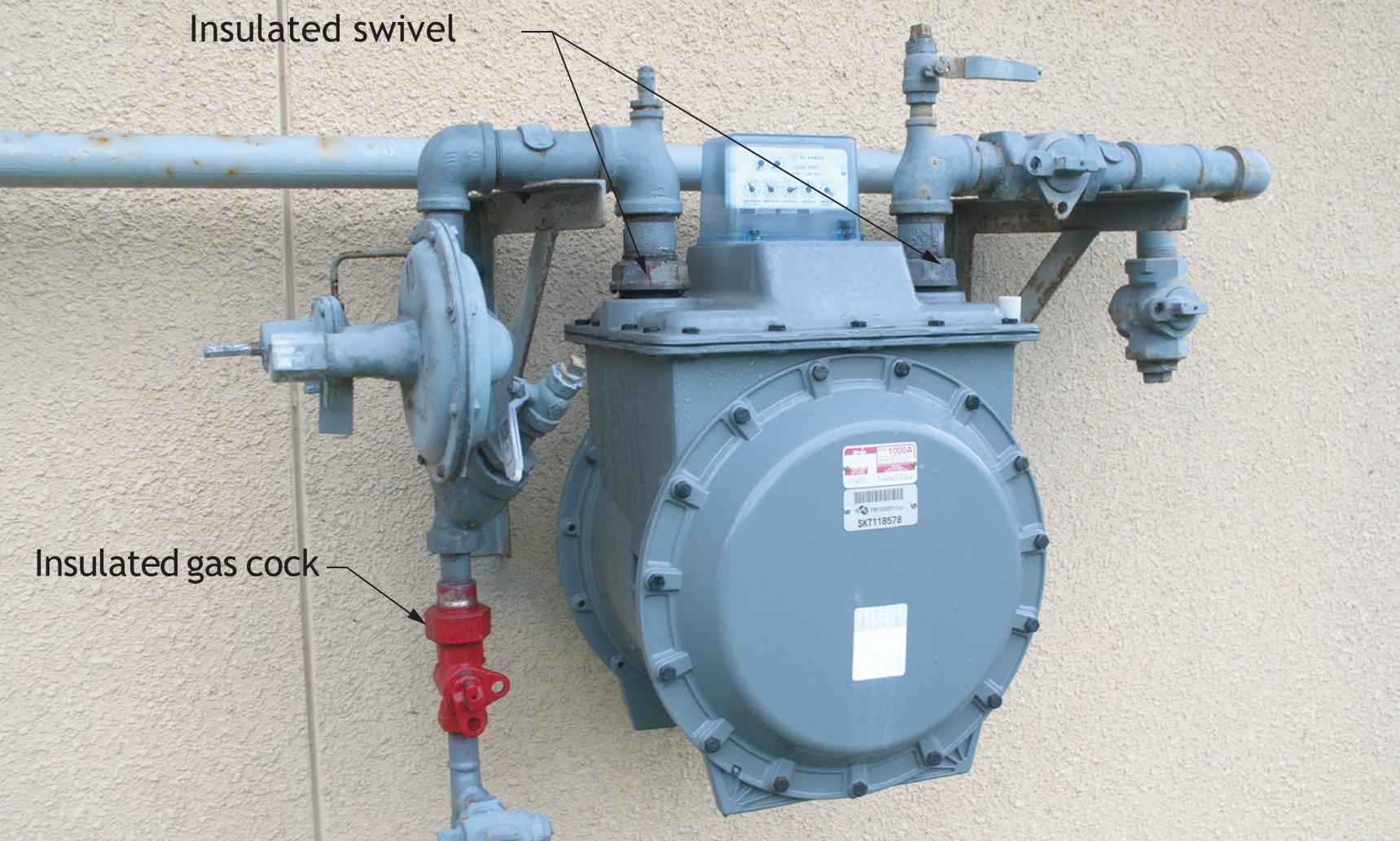
Underground storage tanks and their piping must be electrically isolated from any dissimilar buried metal piping.
Dielectric unions can be made of various metals, such as malleable iron or forged steel, which is either galvanized or black-metal coated.
Dielectric Flange
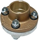
The dielectric flanged pipe fitting shown in Figure 45 is installed between pipes of dissimilar metal, in this case copper tube and steel pipe. The flange has an isolative gasket and bolt isolative bushings. It effectively interrupts the electrical current flow that causes corrosion.
 Caution: Metal piping in buildings is grounded according to Electrical Code requirements.
When a dielectric fitting is installed, it interrupts the grounding safety provided by the grounding connection. This creates a dangerous situation in the remaining piping system downstream of the dielectric fitting.
Additional piping system grounding (bonding) is required, in accordance with the Electrical Code.
Marine and Ship Cathodic Protection
In the marine and ship industry, cathodic protection is applied to shipboard piping systems and also the ship hull itself. Galvanic anodes are attached to ship hulls rather than impressed cathodic protection. Anodes are removed and replaced as regular ship maintenance. Smaller craft boats with non-metallic hulls also use galvanic anodes. However, an electrical conductor connection between the anode and the protected equipment is required.
Water Heater and Water Connections
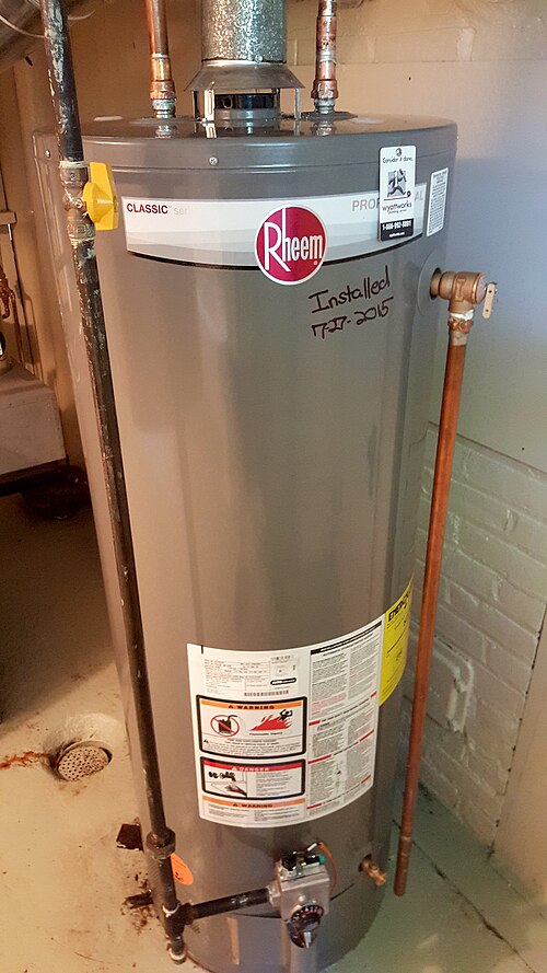
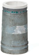
Hot water storage heaters come equipped with internal sacrificial anodes, which should be inspected at regular intervals, as recommended by the manufacturer—typically once a year. Hot water storage heaters can also come with plastic-lined connection pipe nipples. These pipe nipples serve as a dielectric connection to the tank. If the hot water storage heater is equipped with a sacrificial anode and dielectric nipples that provide cathodic protection, then dielectric unions aren’t needed.
Precaution must be taken to not melt the plastic in the pipe nipple when making a soldered connection to copper piping.
Stray Electrical Currents and Pipe Corrosion
The third prong on a standard electric plug is the grounding pin. This grounding pin is a safety component that protects the user from shock in the event of a fault in the tool or equipment. The grounding circuit will dissipate any electrical voltage to an earth-to-ground-rod located in the building’s electrical system. This voltage is dissipated into the ground. The electrical system circuitry itself includes a neutral conductor that is connected at the service panel to the earth-to-ground-rod system. Typically, there is always some small current flow in the earth-to-ground-rod connection. These stray currents can cause in-ground metal piping systems to suffer from accelerated rates of electrolytic corrosion. Any assessment of passive or impressed protection must consider this increased corrosion.
Stray electrical currents and voltages are expected in existing piping systems when the metal piping system is grounded (Figure 51).
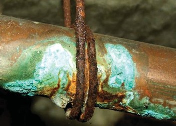
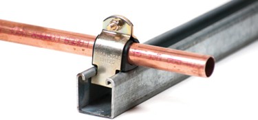
Protective coatings on the buried pipe help reduce corrosion of in-ground piping. Pipe tape insulation, either on the hanger or around the pipe, can eliminate current flow and prevent corrosion.
Safety Issue with Stray Electrical Currents
Stray current is any voltage or current other than what you are expecting. For example, you would not expect a shock from a pipeline from which you have just removed a valve.
Electrical shocks have been documented when service personnel have removed valves, water meters, and other components. To reduce the possibility of shock from these piping systems, install a jumper cable from the pipe to a proper earth ground. This is especially important if the piping system is serving as a pathway for stray current back to the building ground rod.
When a grounding system has been removed or improperly installed, the possibility for shock injury is increased. An individual touching an ungrounded metal piping system will become the conductor for any stray currents. The potential for shock is high. The intensity of the shock depends on a number of conditions including the stray current voltage, amperage, conductibility of the individual, and moisture. Always install a temporary jumper ground.
Field Test for Stray Voltage
There are standard test procedures for detecting stray currents and voltages. These tests should be carried out by a qualified electrician and are not part of this competency.
A quick check for you own safety should be completed with a multimeter with milliamp capability. A common electrical tester pen will also work.
In a properly grounded system, you should not see electrical currents higher than a few milliamps, and the voltage should be less than 10. If you have any doubt, or suspect stray current, contact a qualified electrician.
Water Treatment Pipe Protection
Pipe systems used in hot water heating or steam heating are often treated to avoid pipe corrosion and for greater efficiency.
Pure water (H20) is tasteless, odourless, and colourless in its pure state. However, pure water is very uncommon—natural waters contain various impurities. If not treated, these impurities can form deposits on heat transfer surfaces in boilers and heating piping.
Untreated boiler water may cause the following:
- Metal corrosion
- Reduced heat transfer rates, leading to overheating and loss of mechanical strength
Typical Impurities Found in Water
pH: This is a measurement of the acidity or alkalinity of a substance. You may need to adjust the pH level of water in a hydronic heating system by adding an acid to stabilize a condition that is too alkaline or by adding a base (alkali) if the solution is too acidic. Hot water boiler manufacturers normally suggest a solution that is very mildly alkaline (pH of approximately 7.8) rather than neutral (pH of 7) to prevent corrosion caused by acidic water.
Dissolved solids: These are substances that will dissolve in water. The principal ones are the carbonates and sulphates of calcium and magnesium, which are scale-forming when heated. There are other dissolved solids, which are non-scale forming. In practice, any salts forming scale within the boiler should be chemically altered so that they produce suspended solids, or sludge, rather than scale.
Suspended solids: These are substances that exist in water as suspended particles. They are usually mineral or organic in origin. These substances are not generally a problem as they can be filtered out.
Dissolved gases: Oxygen and carbon dioxide can be readily dissolved by water. These gases are aggressive instigators of corrosion.
Scum-forming substances: The use of water softeners, iron filters, UV-sterilization and other water treatment devices may be necessary in order to correct any conditions that are undesirable for the water’s intended use. Mineral impurities that foam or scum: usually soda in the form of a carbonate, chloride or sulphate.
Corrosion in Fire Sprinkler Systems
Wet and dry fire sprinkler systems are primarily composed of metal pipe, water, and trapped or compressed air. Any environment that has oxygen, metal, and untreated water in prolonged contact with each other is subject to corrosion (i.e., rust). Bacteria and other corrosion mechanisms can accelerate existing corrosion in fire sprinkler systems.
Microbiologically Influenced Corrosion
Microbiologically influenced corrosion (MIC) is an electrochemical process involving bacteria that can accelerate previously occurring corrosion in both wet and dry fire sprinkler systems. MIC always involves bacteria but does not occur by itself. In recent years, thin-wall piping has been introduced, so the effects of corrosion appear more quickly.
Oxygen corrosion is also common in fire sprinkler systems. Evidence of high corrosion exists especially at the air/water interface at high points in the fire sprinkler system where air accumulates.
The prevention of sprinkler pipe corrosion is becoming a major issue in this trade.
Corrosion Indications in a Fire Sprinkler System
Pinhole leaks can be caused by a variety of corrosion mechanisms but are most often attributed to microbiologically influenced corrosion.
To prevent corrosion in fire sprinkler systems:
- Complete an assessment of the system to determine if a corrosion situation exists
- Treat the system with water treatment chemicals
- Install air vents to remove oxygen
Chemical Treatment
Portable chemical injection systems can be used for injecting corrosion inhibitors into fire sprinkler systems to prevent corrosion caused by MIC.
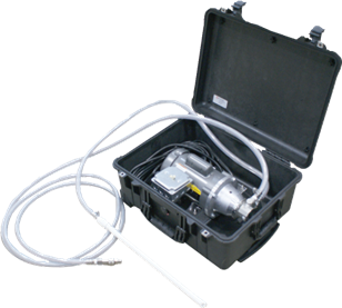
Removing Air (Oxygen)
Air removal means are used to reduce corrosion in a fire sprinkler system.
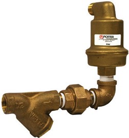
An air vent will reduce the amount of air trapped in a pressurized fire sprinkler system. Reducing the amount of air reduces the effects of oxygen corrosion. Air vents should be installed at the collection point for air in the high points in the sprinkler system.
Internal Protection Using Chemical Treatment
Chemicals used in fire sprinkler systems should be environmentally safe. One example of a chemical that is designed specifically for fire protection systems is Potter’s Pipe-Shield®, a patented, biostatic, environmentally friendly corrosion inhibitor. This pipe shield protects wet, dry, and pre-action fire sprinkler systems from both microbiologically influenced corrosion and oxygen corrosion, and is completely nonhazardous and biodegradable, with a neutral pH. It does not contain biocides and pesticides commonly used to control or kill bacteria, so it is safe for the environment.
Protection of Buried Pipe Against Flotation Damage
Pipe buoyancy must be considered whenever there is a risk of flotation. When the water table is above the bottom (invert) of the pipe, the surrounding water creates an upward (buoyant) force. This force is equal to the weight of the water displaced by the pipe. If the upward force is greater than the combined weight of the pipe and its contents, the pipe will float.
Conditions that can lead to a pipe floating out of a trench include the following:
- Pipelines installed in ground with a high water table or where flooding is a possibility
- Pipelines installed under lakes, oceans, etc.
- Flooding of trench before and after backfilling
To avoid flotation buoyancy of pipe, proper installation and/or anchoring of the pipe are critical. The uplift buoyancy of a buried pipeline depends upon the:
- Weight of the pipe material
- Weight of the volume of water displaced by the pipe
- Weight of the liquid load carried by the pipe
- Weight of the backfill material
- Specific gravity of the pipe material and the volume of water displaced
When considering the buoyancy of sanitary and storm lines, you must first determine buoyant force when the pipe is empty, which is when the buoyant force would be the greatest.
To prevent flotation, proper installation and/or anchoring is required. Methods may include:
- Adequate backfill
- Concrete weights or collars
- Ground screw anchors
Flotation Buoyancy Protection Methods
The weight of backfill material is usually sufficient to prevent uplift of piping and hold the pipe in the ground. When backfill alone is not heavy enough, additional methods such as concrete weights or ground screw anchors can be used. Weights such as concrete collars of sufficient size and weight can be positioned on the pipe to prevent flotation. The pipe can also be strapped to concrete pads placed in the trench.
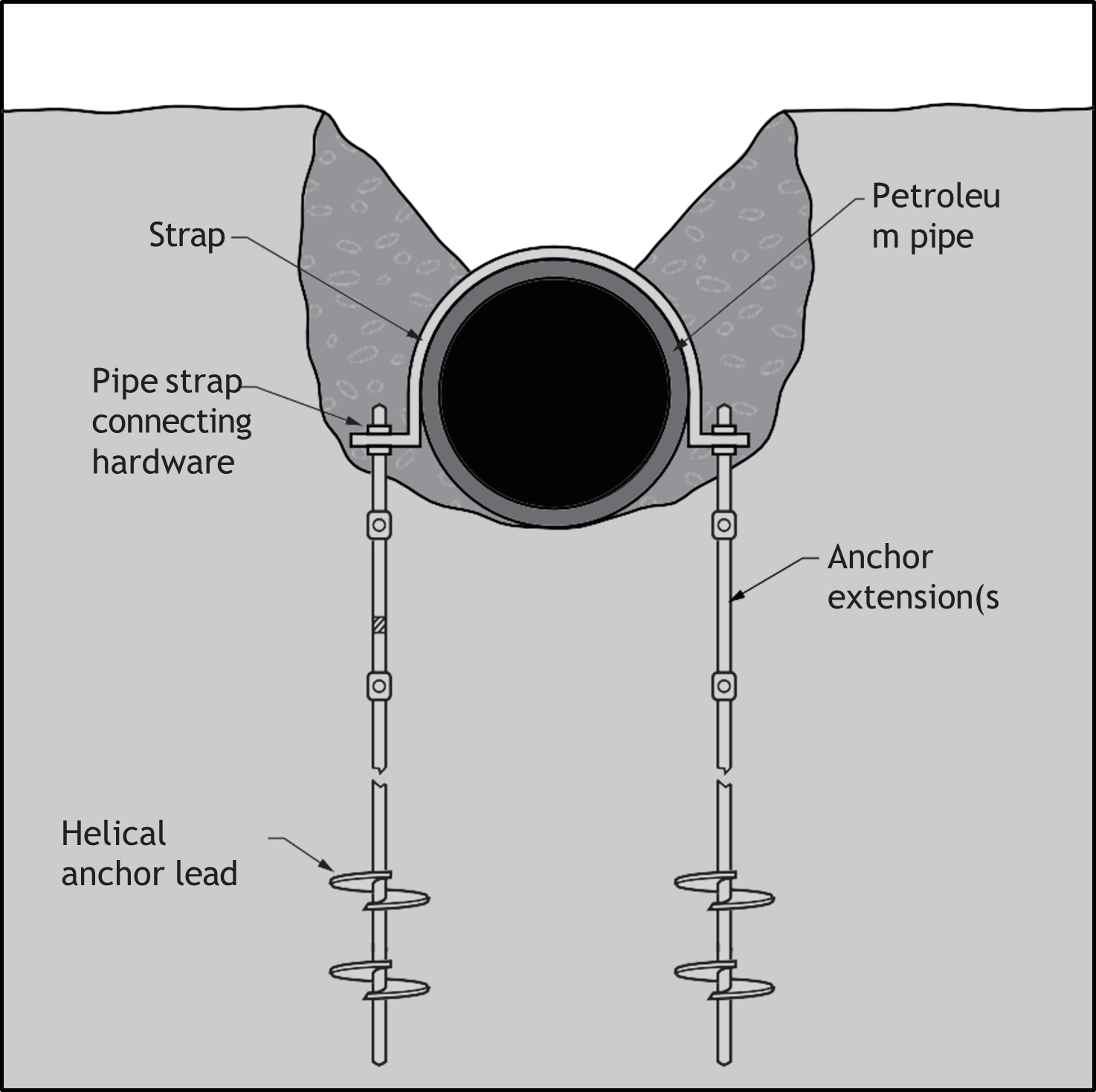
Flotation Protection During Trench Installation
Piping installed in a trench often has to be inspected before backfilling. Proper bedding is required, and the pipe is tested under pressure for leaks. The tests may include pressurizing with air, inert gas and/or water. The pipe cannot be completely backfilled and must be left visible for inspection for a period of time. During this time, the exposed trench might be inundated with groundwater or rainfall runoff. Buoyant upward forces on the pipe may be sufficient to lift the pipe out of the bedding materials. When pipe grades are disturbed, the pipe must be repositioned, which can be costly. Pipe flotation restraint may be accomplished simply with adequate backfill. In cases where adequate cover cannot be achieved, alternate methods for restraining the pipe are available.
To reduce the chances of pipe flotation, it may be acceptable to partially backfill portions of the piping with enough weight to resist flotation before inspections are completed. You should consult with the authority having jurisdiction before backfilling prior to inspection.
Buoyancy of Other Underground Equipment
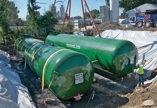
Buoyancy also applies to storage tanks installed below ground; for example, septic tanks before they are filled with water and underground gasoline and oil storage tanks. Septic tanks should be filled at the time of installation if flotation is a concern. Underground storage tanks are normally braced against flotation buoyancy using in-ground anchor systems such as strapping the tank to a concrete pad.
Pipe Expansion from Sunlight
The exposed top of bedded piping can expand when heated by direct sunlight. The expansion may cause the pipe to warp and arch up and lift out of the bedding material. Bedding material such as sand can then fall under the arched portion of the pipe. When the pipe cools, it cannot settle back into its original position, and repositioning is required. To prevent this situation from occurring, lightly cover the pipe with just enough backfill to prevent sunlight exposure. The light cover can be brushed back to expose the pipe markings for the inspection authority and to check that plastic pipe, such as ABS (black surface) and PVC, have high coefficients of expansion and are susceptible to expansion and degradation caused by sunlight exposure. Pipe installed above ground and exposed to direct sunlight may need to be protected by insulation, protective pipe wraps, or shielding.
Refer to D-4 Penetrate Structures for information on pipe wrap and shielding.
Pipe Storage, Shipping, and Handling
Pipes can be distorted and damaged by improper storage, including:
- Improper handling and stacking
- Exposure to sunlight
- Excessive heat or cold
Pipes and fittings stored outdoors for an extended period should be protected according to the manufacturer’s instructions.
General Pipe Storage Conditions
The following give guidelines for pipe storage conditions:
- Exposure to excessive heat should be avoided to reduce the risk of pipe distortion.
- If plastic pipes or fittings are to be stored outdoors for extended periods of time, they should be protected as directed by the manufacturer. Plastic pipes may be affected by exposure to sunlight, especially if exposed for extended time periods and outside of protective cover. Bowing of the pipe can also occur.
- Correct stacking of some pipe can result in bowing and distortion (out of round). It can be difficult to attain correct even and continuous grade during installation if the drainage pipe is bowed. You may be able to correct a bow by exposing the opposite side of the pipe to sunlight before installation. However, it is best not to purchase bowed pipe.
- When purchasing pipe, check for damage such as deep scratches, cracked ends, out of round, etc.
- When stacking pipe at the job site, set the pipe on evenly spaced, level runners to prevent sagging. Place wedges or blocking to stop the pipe from rolling off the runners.
- Pipe delivered on pallets is often banded. Be sure that cutting the band does not cause the pipe stack to collapse uncontrolled. If the pipe is not on a supporting cradle, block the stack before cutting the banding.
- When stacking pipe that has hub ends, alternate the hub and spigot ends with the ends protruding so that the pipe barrels will lie flat.
- When unloading alongside a trench, stack the pipe on the opposite side of the trench from the excavated soil pile. Installing large and heavy pipe will be easier from the clean side of the trench.
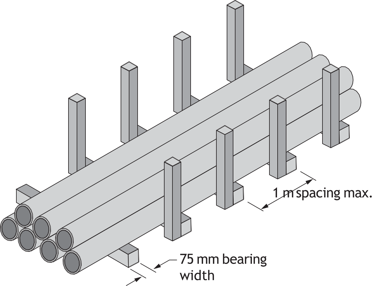
Trench Depths and Pipe Protection
Buried pipes must be able to withstand the forces trying to damage or crush the pipe. Pipe leaks can be serious, especially when combustible liquids and gases, sewage and water supplies are involved. Pipe protection and proper burial are important to prevent pipe damage during installation and regular use.
Factors affecting the depth of a trench and the protection of the installed pipe include the following:
- Type of pipe and schedule (wall thickness strength)
- Job site terrain
- Job specifications
- Code regulations
- Required slope
- Vehicle traffic
- Weight of the fill material
- Proper compaction of the soil below and surrounding the pipe
General Trenching Guidelines
You must consult job specifications and code regulations within the area jurisdiction.
For details on trench depth for plastic pipe, refer to code books and manufacturers’ documentation.
Trenching Pipe Protection
Normally, you need to follow the job site excavation engineering specifications, plans and the local code requirement. The following information is non-specific but will give you an idea of the typical requirements for trench construction to protect buried piping.
Typically, a trench would be constructed as follows:
- As narrow as practicable at the pipe depth
- Wide enough to provide space to work on the pipe and proper jointing
- Where soil conditions are unstable, trenches may need to be wider to the depth where the trench is unstable and narrow at the pipe depth where the soil is undisturbed and stable. Trench walls may need to be shored.
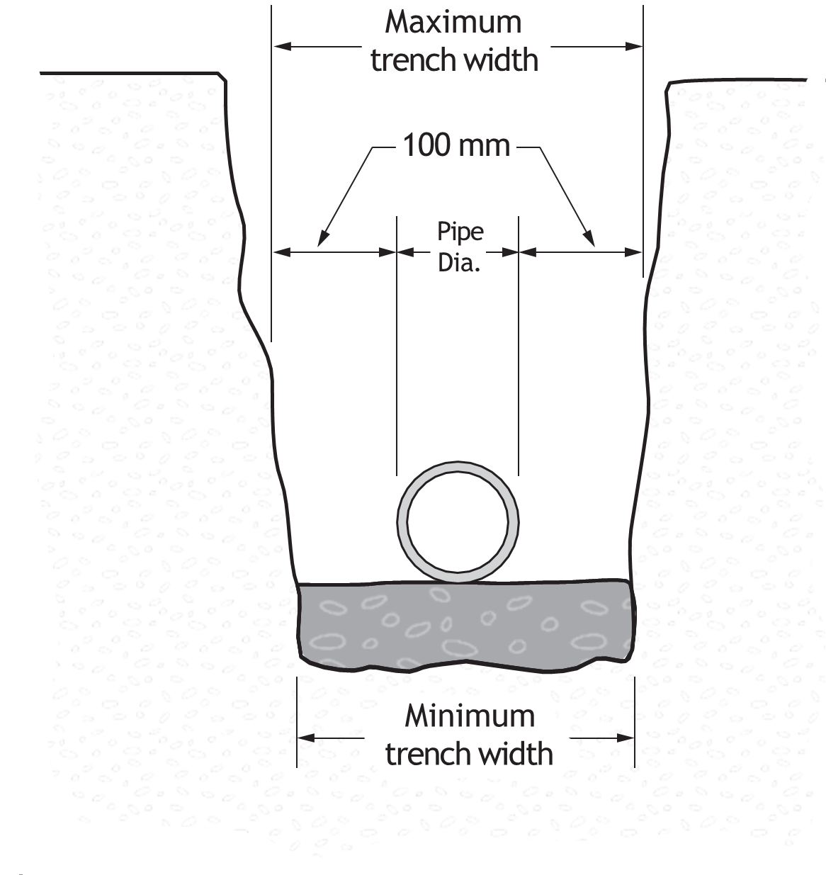
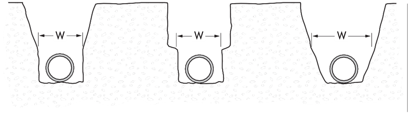
Table 1 lists examples of trench measurements under stable conditions.
|
Pipe Diameter |
Normal Trench Width |
|
100 mm (4 in.) |
400 mm (16 in.) |
|
150–200 mm (6–8 in.) |
600 mm (24 in.) |
|
225–300 mm (9–12 in.) |
750 mm (30 in.) |
|
375 mm (15 in.) |
900 mm (36 in.) |
Backfill Material and Compaction of the Soil
Pipe bedding and backfilling material should not:
- Be placed in a ditch where standing water is present
- Include large stones, boulders, cinders, frozen earth or building site debris.
The pipe should:
- Not rest on solid rock without suitable bedding protection
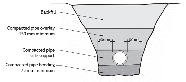
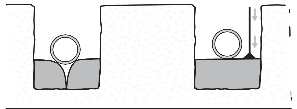
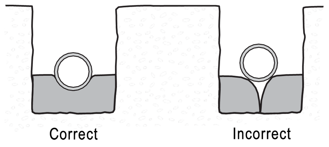
- Be laid on compacted level bedding that supports the full length of the pipe barrel (sand, gravel, crushed rock or good natural sandy soil; no large boulders, etc.)
- Be covered in sand, gravel, crushed rock or good natural soil (no large boulders, etc.) compacted to a minimum of 300 mm (12 in.) above the pipe
- Be covered with natural excavated soil consistent with the surrounding soil for the remaining backfill material
Protecting Pipe During Backfilling
- Bedding may not be required in all cases. Soil conditions at the trench bottom may be adequate to support the pipe continuously without additional bedding.
- When bedding is required, the bedding must be compacted before the pipe is laid.
- Pipe overlay backfill is best hand-shovelled around the pipe and continually tamped snugly to the pipe.
- Before covering the pipe, it is tested and inspected as soon as possible.
- Shortly after inspection and approval, overlay backfill is carefully added by shovel or machine. Care must be taken that no heavy rocks are dropped on the pipe.
- Overlay backfill and compacting continues to a depth of approximately 150 to 300 mm (6–12 in.) over the pipe. Plumbing codes may require a minimum of 300 mm (12 in.) coverage above the pipe.
Compacting provides continuous support for the pipe. Final backfill is complete and compacted. Limited amounts of water can aid compaction.
Damage from Vehicles
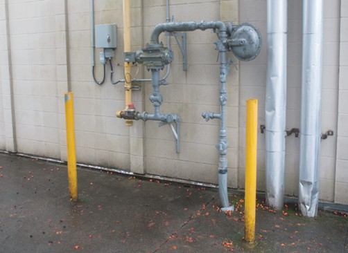
Damage to piping due to contact with vehicular traffic occurs in locations where services enter a building, such as above-ground gas services. Damage to piping occurs in parking garages or warehouse facilities frequented by vehicular traffic. Protection methods include barriers such as bollards or curbs. These barriers must be constructed to take the force of contact away from the pipe.
The location and design of barriers to protect pipe from vehicular traffic is often done by the design engineers and, in many cases, is addressed in building code regulations.
 Self-Test D-1.4: Describe the Methods of Manufacture of Piping and Tubing
Complete Self-Test D-1.4 and check your answers.
If you are using a printed copy, please find Self-Test D-1.4 and Answer Key in the Appendix at the end. If you prefer, you can scan the QR code with your digital device to go directly to the interactive Self-Test.

References
BC Industry Training Authority. (2019). Piping trades apprenticeship program: Use Tools and Equipment—Level 1 harmonized [Binder]. Crown Publications, Queen’s Printer for British Columbia. https://www.crownpub.bc.ca/Product/Details/7960000261_S
- Plumber: Competency D-1 Prepare Pipe
- Steamfitter: Competency D-4 Layout and Install Piping and Tubing
- Sprinkler Fitter: Competency D-1 Prepare Pipe and Tubing
CSA Group. (n.d.). CSA Group: Testing, inspection, and certification. https://www.csagroup.org/
FM Approvals. (n.d.). FM Approvals. https://www.fmapprovals.com/
Potter Electric Signal Company. (n.d.). Potter Electric Signal Company. https://www.pottersignal.com/
Media Attributions
All figures are sourced from Industry Training Authority (2019) and/or Camosun College (2019) and are used under the Creative Commons Attribution 4.0 (CC BY 4.0) licence unless otherwise noted. Images copyrighted by the BC Industry Training Authority are licensed under a Creative Commons Attribution-NonCommercial-ShareAlike 4.0 (CC BY-NC-SA 4.0) licence.
- Figure 3 Geotextile-GSI by Marilyn475 from Wikimedia Commons is used under in the public domain.
- Figure 4 Steel casing pipe by annawaldl on Pixabay is used under the Pixabay Content License.
- Figure 12 Example of heat trace thermostatic control is ©2014 Environmental Technology Inc. Used with permission
- Figures 15-17 are examples from the CSA Handbook and are used with permission.
- Figure 48 Dielectric flange fitting is courtesy of Watts and is used with permission.
- Figure 49 Gas water heater tank by Tim Evanson from Wikimedia Commons and is used under a CC BY-SA 2.0 license.
The upward force that pushes objects up when they are in water. (Section D-1.4)
When a pipe gets bigger because of heat. (Section D-1.4)
Chemicals that easily turn into gases and can be harmful to people and the environment. They are often found in paints, coatings, and solvents. (Section D-1.4)
A coating that can be applied in one thick layer to provide full protection, instead of needing several thinner coats. (Section D-1.4)
The gradual destruction of material, usually metals, by chemical reaction with its environment. Typically, it refers to the electrochemical reaction with an oxidant such as oxygen. (Section D-1.4)
A protective fabric used to cover pipes and prevent damage during installation. (Section D-1.4)
A long, narrow hole dug in the ground to install pipes. (Section D-1.4)
Methods used to stop pipes from freezing and bursting. (Section D-1.4)
Material used to keep heat in or out of a pipe. (Section D-1.4)
An electrical cable used to keep pipes warm and prevent freezing. (Section D-1.4)
Corrosion caused by an electrical reaction between metals and their environment. (Section D-1.4)
A metal from which current flows. (Section D-1.4)
A metal through which current flows. (In an electrochemical reaction, the anode is the metal that corrodes.) (Section D-1.4)
A method used to control the corrosion of a metal surface by ensuring that the metal is the cathode in an electrochemical process. Normally, this process requires attaching or connecting the metal to a less-noble metal. (Section D-1.4, Table 5)
A method used to reduce corrosion by separating different metals and controlling electrical current so the pipe is protected from rusting. (Section D-1.4)
A small handheld tool that detects if electrical voltage is present in a wire or device without touching exposed metal parts. (Section D-1.4)
Corrosion caused or sped up by bacteria. (Section D-1.4)
A chemical reaction that involves electricity. (Section D-1.4)
Corrosion caused by oxygen reacting with metal. (Section D-1.4)
A very small hole in a pipe that can cause leaks. (Section D-1.4)
A device that removes trapped air from a piping system. (Section D-1.4)
This is a measurement of the acidity or alkalinity of a substance. You may need to adjust the pH level of water in a hydronic heating system by adding an acid to stabilize a condition that is too alkaline or by adding a base (alkali) if the solution is too acidic. Hot water boiler manufacturers normally suggest a solution that is very mildly alkaline (pH of approximately 7.8) rather than neutral (pH of 7) to prevent corrosion caused by acidic water. (Section D-1.4)
When a pipe rises or lifts out of the ground due to water pressure. (Section D-1.4)
The level below ground where the soil is fully saturated with water. (Section D-1.4)